My first ever digital multimeter was a Heathkit IM-1212. I built it from a kit when I was a teenager (thanks, Dad.) A whopping 2½-digit, 200-count unit with 1% ± 1 digit basic DC accuracy. Barely a step up from a basic analog VOM, but at least you didn’t have to count divisions or figure out where the decimal point went. The display used two Nixie tubes for the numbers. Later on I converted it to an LED display, which pretty much destroyed its ‘coolness’ and ‘retro’ appearance. Not very photogenic or blog-worthy nowadays…
But roughly ten years later, a friend asked me to build a new-old-stock Bell & Howell IMD-202-2 kit. It’s actually the exact same meter as the Heathkit, except with the Bell & Howell name on the front. For reasons I don’t remember, the friend never took possession of the completed unit, and it has been stored away for a long time. But now it’s time for a look!
This meter uses a very simple design. There is only one op-amp, an LM301 which comprises the AC converter. There are a few 7400-series chips: two 7490 decade counters, a dual J-K flip-flop for the leading ‘one’ digit and over-range indicator, and a couple of quad-gate packages for some timing tasks. The Nixie tubes are driven with open-collector 7441 BCD-t0-decimal decoders. Most of the analog-to-digital converter (ADC) is implemented with discrete transistors.
The ADC is a single-slope voltage-to-time converter with a full-scale input of 2 volts. A FET constant-current source charges a capacitor to create a ramp signal. As soon as the ramp builds enough voltage to turn on a BJT (about 0.6V), a clock signal is gated through to the display counters. This ramp is compared to the input voltage using another BJT, and when it reaches the input voltage plus the BJT turn-on voltage, it gates the clock signal off and discharges the cap. The larger the input voltage, the longer the counters are allowed to count. That’s basically it!

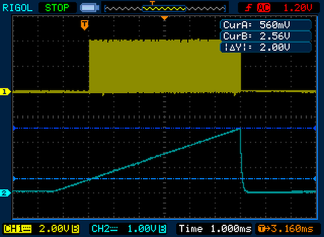
This shows the ramp signal and the clock during a single ADC conversion cycle for a 2.0V full-scale signal. Notice the clock does not start until the ramp has reached about 0.6V. The clock stops when the ramp is 0.6V above the input. This is because the ADC is using BJTs to detect the input and ramp levels.
The clock signal is generated from a basic two-transistor astable multivibrator circuit. System timing is derived from a sample of the AC mains frequency, therefore the system performs 60 conversions per second by counting for half of the 16.67ms cycle and displaying for the other half. The display tubes and lamps are driven from a high-voltage winding on the transformer that has been half-wave rectified. This insures that tubes are displaying for half a cycle, and blanked during the other half, while the counters are counting. Clever.

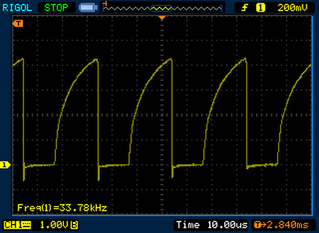
Clock signal generated by a classic two-transistor multivibrator circuit. This one measures 33.78kHz. The frequency affects accuracy, and is affected by the stability of the film caps and carbon composition resistors in the multivibrator.

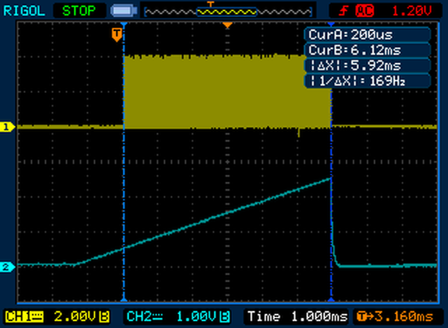
Again, measuring a 2.0V full-scale input. Notice the counting period is 5.92ms long. With a 33.78kHz clock the period is 29.6μs, so the number of counts is 5920/29.6 = 200.
The long-term accuracy of this design is not great, since it depends entirely on the stability of the clock and ramp-generation components, and not a stable voltage reference. In fact, I remember re-calibrating my unit quite regularly when the temperature changed significantly. The Heathkit factory provided a zener diode and two voltage-divider resistors in a separate envelope in the kit. The three components were measured on factory equipment and the voltage was recorded on the envelope. This became the unit’s unique DC calibration voltage. A test point on the circuit board allows the user to calibrate (or re-calibrate) the meter without needing extra equipment.
Now that you’ve suffered through the EE stuff, let’s take it apart and look inside.


Nixie tubes are smashing indicators, enjoyed your write up 🙂
I had a frends racal frequency counter here about two years ago, the nixie tubes were very sad looking, ultra low emission 🙁 shame i didnt have some.
He liked led displays, so after taking a look at the bcd to nixie driver chips (SN74141)
i scanned my r.s semiconductor book and found a (4511 bcd to 7 segment led driver).
With resistors and 4511’s i made an “L” shaped display board, wired it up and it worked smashing. (h.v cut at source just in case).
I realise the input logic of the 4511 was not a spot on match for the 74xx stages but it was not critical with the oh so slooooooow speed lol 🙂
Still works spot on, and behind the thick red filter i added the leds didnt look out of place, quite original looking really.
Your 8050a led mod is really handy for people like me 🙂
Thanks, Harvey. Glad you enjoyed it. I did something similar with my original Heathkit IM-1212, using 7446 BCD-to-7segment decoders. Looked OK, but no more Nixie glow. Heathkit sold other models with LED displays. I think they used the exact same design as this one, except of course for the display drivers.
The 8050A LED mod is not overly complicated, but it is a tedious process.
Nice site. We are probably about the same age. I played with a lot of tube stuff in the early and mid 70’s as this was when it was cheap and surplus.
I have several of these units. It seems I have been finding them everywhere lately for cheap.
The Nixies alone are worth picking them up, but I hate destroying gear just to get the Nixies. A 2 1/2 digit meter is not much, but this stuff is very cool. I would like to get mine going again.
Do you have the manual/schematics for these?
Thanks for the comments. Low fifties here. 🙂 I do have the manual and schematics but unfortunately I do not own a document scanner. And I heard some ex-Heathkit employee purchased all the copyrights on old Heathkit manuals and was actively keeping them off the internet?
Wow! That brought back memories. I took the Bell & Howell Digital Industrial Electronics course in the mid 70’s and built one of these. After looking at your photos, I went out to the garage and found the one I built. Its at least 35 yrs. old, maybe 40! Plugged it into a “dim bulb tester” to see if it was ok, and it worked! Not sure how accurate it is, but I would probably only use it for a line voltage monitor or something like that. As I recall its input impedance was only 1 meg, so it tends to load a circuit down a bit. Using this thing, I sure learned a lot about electronics from the hands-on experiments in the B&H course. You really sent me on a neat trip down memory lane. Thank you!
Glad you enjoyed that, Mark.
ok,polisch -cacko!
I picked up an IM-1212 for like $25 a couple years ago. Unfortunately all of the leads I have are the reverse banana jacks, so I haven’t been able to verify the functionality. But it powers on, the nixies light up, etc.
I’ve been looking for the 1212 manual, but have been unable to find one online. I have seen the 1202 PDF manuals.
It’s a neat piece of tech, just because it uses Nixie tubes in a ‘real’ application as opposed to people now a days just making Nixie Clocks.