
") Properly-designed multimeters that are suitable for professional and trade use have a number of components, usually near their input jacks, that are for the sole purpose of protecting both the user and (secondarily) the multimeter itself from over-voltage and over-current situations. Everybody knows about fuses and can probably recognize them right away. But the fuses are only used to protect against having too much current passing through the meter and test leads when using the Amp and/or milliAmp jacks.
Properly-designed multimeters that are suitable for professional and trade use have a number of components, usually near their input jacks, that are for the sole purpose of protecting both the user and (secondarily) the multimeter itself from over-voltage and over-current situations. Everybody knows about fuses and can probably recognize them right away. But the fuses are only used to protect against having too much current passing through the meter and test leads when using the Amp and/or milliAmp jacks.
[Recommended viewing: EEVblog #373: Multimeter Input Protection]
There are a number of other protective components you may find near a multimeter’s input jacks. Some are connected in parallel with the input source, and are meant to trigger when the voltage across the input reaches a dangerous level, becoming a low-impedance path to essentially short-circuit the energy away from the rest of the meter’s sensitive circuitry. These components are usually spark gaps and/or varistors (MOVs).
Others are connected in series, and will become an open circuit or high impedance when something goes awry and too much energy is being absorbed. These components are usually PTC thermistors and/or fusible resistors. The latter component masquerades as a regular high-wattage power resistor, and is sometimes also described as “flame-proof”. Thermistors should return to their normal impedance after the overload is removed and they have cooled down, but once a fusible resistor has “blown”, it no longer functions.
Many (but not all) models of Fluke multimeters include a fusible resistor in series with the Volt/Ohm input jack. The meter shown in this repair is a first-generation Fluke 87. The metal-film fusible resistor is designated R1 (part #832550) in the model 87 parts list.
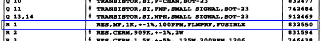
In the service manual it is described generically as a “1kΩ 2W fusible resistor.” This resistor is a common failure point for a unit that has been subjected to an over-voltage situation. Tried to measure the output of an electric fence, maybe? (Don’t do that.)
A meter with an open fusible resistor may power up and look normal, but upon trying to make measurements, it can act rather goofy. Let’s look first at the symptoms of an open fusible resistor, and then find and replace it.
[Click on any of the following pictures in this article for a larger view. All graphics used in this article are also available as an image gallery.]

DC voltage is selected on the function switch, but when a DC voltage is applied the meter always reads zero.

Resistance is selected and the leads are left open. A functional meter would display a steady OL, but this one displays positive and negative random numbers and sometimes flashes OL. If the beeper is turned on, it will beep randomly.

Shorting the leads would normally cause the meter to read a value near zero, say about 0.2 ohms. But this one flashes OL rapidly. (The dim digits in the photo is a result of the flashing.)

On the diode check range, with no leads connected, the meter would normally read OL. Instead this one seems to be stuck at 0.000V.

Attempting to measure 120VAC mains results in a very small unsteady voltage being displayed. The broken resistor is capacitively coupling a small voltage into the front end.


Goofy meter is now acting sane again!
Update: After I prepared this article I discovered that DigiKey (and Mouser, Newark, etc.) no longer stocks the replacement resistor I used. The following are possible sources of replacement parts. Note that non-Fluke replacements are not guaranteed to return the device to its original safety specifications.
| Part No. | Description | Voltage | Possible Source |
|---|---|---|---|
| 832550 | Original Fluke part | Fluke Service | |
| Ohmite OY102KE | Ceramic Composition Resistor 2watt 1K 10% Surge | 400V | Mouser, Digi-Key |
| NTE F2W210 | 2W Fusible Power Oxide Resistor | 300V | Moyer Electronics |
Dear Mr. ModemHead first of all respect of your skills to repait dmm model and your blogger site. I found your blogger site after i looked for adding a summer to my low cost dmm (Digital Multimeter DM 830 E) when I testing a wire to hear a sound and not looking on my dmm all the time.
Please can you help me to add a summer for DM 830 E and explain how it works?
Thank you
supporter
I assume you refer to a ‘beeper’ or ‘buzzer’ for continuity testing. You will need to add a piezo element, a comparator, an oscillator, and a gate of some sort to allow the comparator to turn the piezo element on and off. When a low resistance is placed across the inputs, the voltage across it drops close to zero. The comparator detects when this voltage goes below a set threshold, and turns the beeper on. Here is a schematic for a simple 830-style DMM with continuity feature. I added notes to point out the how the continuity works.
Hi yes your ´re right! thank you for the fast answer!!!!!
ok I will try !!!
Keep doing your blogger site !!! To repair dmm is good to ask peaople like you, you are very special.
best regards
supporter
Back again to sample your wisdom and humor 🙂
I too have two of the cheap 830 digitals that “supporter” is in the process of modifying, and yes they are cheap but for a simple icl7106 clone blob chip they work quite well really.
The dc voltage and resistance is accurate enough for ordinary go/no go testing.
I must admit ive never noticed the fusable resistors before, but im not in the habit of applying voltages where they should not be, yet!! ha ha 🙂
Hmm fluke 87, a wheelbarrow resident? 😛
I must get a fluke portable multimeter before you kidnapp all the available ones floating around :-), the trouble is the plethora of models confuses my small and often confused brain.
I have also noticed your 806 ohm resistor that appears to be marked 805.8 ohms, your standards are slipping by calling it 806 ha ha 🙂 🙂 leg pulling 🙂
As allways a delight to read your writeups 🙂
Dear harvey, you are a plonker, you have given the impression that the two 830 multimeters you have are being modified by “supporter”.
You are english and your spelling&punctuation is rubbish.
With no respect
Harvey the confised 😉
Glad you enjoy my write-ups. Come back anytime. I have a few more in the queue at the moment. Being confised doesn’t hurt, does it?
The ICL7106 is a wonderful invention. Makes it simple as pie to make a very accurate DC voltage measurement. And it’s what, a 30+ year old design? That’s why the 830 cheapies are even useful at all. Safety and reliability is of course, something else entirely, and not to be found in those ubiquitous little boxes.
You’re right, Fluke model numbers can be confusing. That’s what happens when the marketing department gets involved I guess.
As for the resistor, well look at this and then you decide what to call it. 🙂
Ha ha sorry ive been hitting the wrong keys again 🙂
Confised… ha ha thats my kind of confusion+pissed, ha ha 🙂
Yep your right (no supprise :-> ), 806 ohms at +/- 2.015 ohms, and i bet its even better than that, manufacturers tend to show the worst values on some things.
Im sorry im so crap at spooling and p.un’c”tu;at!!.ion mate, ive allways had trouble with reading/writing/maths oops math and general learning, butt im shure u stand under wat im slaying lol 🙂
Hi Mr Modem I have several Fluke 25 meters.I can not find a source for the 1k 2w fusible resistor. is there another way around this problem,I do not want to fit a standard resistor because of the safety issue.Thanks for your help in the past.N Clark
The last ones I got were from Moyer Electronics. The folks there were very friendly and helpful even though my order was small. The part is not an exact match, but it’s pretty close.
Hi thanks for reply.I tried moyer they will not accept orders outside there country.I have located the F2W210 resistors from Wholesale electronics.inc.thanks again for your help N Clark
Sorry I failed to take into account your location. Glad you found an alternate source.
Thanks for this writeup I would not have known what that part was! I have a Fluke 27/FM that needs a similar fusible resistor in series with its input. Moyer does have the NTE part you mention, but they want $10 to UPS this $1 part.
How about putting four 4.7K 1/2 watt fusible resistors in parallel for this purpose? They’re 54cents and are carried at my usual supplier (DigiKey). I think I can fit them in there.
http://www.digikey.com/product-detail/en/NFR25H0004701JR500/PPC4.7KBCT-ND/614262
Thanks,
Keith
Hi, Mr Modemhead,
Thanks for all these helpful informations! I have a Fluke 27/FM that needs a the fusible resistor and the one beside it (220k) which is also open. I did not know that component was a fusible resistor until I read your article indicated by one guy (Marvin) from Estonia (http://www.eevblog.com/forum/testgear/fluke-27-27fm-side-by-side-tear-down/msg386093/#msg386093).
Thanks a lot!
Paulo
Hi again!
Please, the rt1 (.022k 1000) in series with the fusible resistor is also open. Can I replace it with a fixed 20 Ohms resistor?
Tkx
RT1 is a 1K-ohm @25C PTC (positive temperature coefficient) thermistor rated 1000V, 40% tolerance. It acts like a self-resetting fuse. Replacing it with a 1K fixed resistor will allow the meter to function, but will greatly compromise its input protection scheme.
Thank you so much for your prompt response and nice explanation.I wrongly thought the .022k stamped on the component meant its ohmic value.Before doing the “adaptations” I’ll try to get the right parts thru a friend that works with electronic instruments. He may have some used spares.
Best regards.
Sorry to bother you with the same matter but I found out that the component I was talking about is a capacitor (C3) and not the RT1. The problem is that I can’t find the service manual for Fluke 27FM. Instead, I was looking at the Figure 4-2 ( A1 Main PCA ) of Fluke 27 service manual which has RT1 at the same place of C3 on the 27FM main board. After analysing the schematic diagram of Fluke 27 I noticed it does not have the fusible resistor R1 (it’s a 3.5K 5W) and R2 has a value of 1M (220k for Fluke 27FM). Anyway, I made a stupid mistake. If you take a quick look at link below you’ll see what I’m talking about:
http://www.eevblog.com/forum/testgear/fluke-27-27fm-side-by-side-tear-down/msg385939/#msg385939
In case you know how to get the Fluke 27FM Service Manual over the internet, please be so kind to informe me.
Thanks and best regards.
I think the “/FM” model was only for the military, so there may not be a service manual circulating for it. My PDF copy looks like it’s for the more recent yellow 27 models. I do have a hardcopy military-style “Operator’s Manual” for the 27/FM, but it has no service information. I’m reasonably sure the 8025B will be very close to the 27/FM, except for the RMS converter section. The manual for that is available.
I now understand why “RT1” and the “.022K” didn’t make sense. C3 is a 0.022uF capacitor, the K is the tolerance (10%), and it is rated for 1000V. It is the coupling (DC-blocking) capacitor for the AC functions. The thermistor on this older model is the gray rectangular component just north of the 5 green blobs which are varistors.
You are correct, the “/FM” model was for the military. According to the seller, this one came from the military when they sold a bundle, some in bad, others in pretty good condition. I will call a friend of mine that works at a Air Force PMEL first thing on monday to see if he can get me some scraps and a copy of the service manual that can send to you in case you’re interested in. By the way, I took a PMEL course in 1984 at Lowry AFB and worked with calibration til 1998. I worked most of the time repairing Tek Scopes, specialy 465 M, signal generators and Spectrum Analyzers before changing to another area. So, I’m having a lot of good memories reading your posts.
Thanks again for all your valuable informations.
Hi,
I have a Fluke 75-2 with a blown R20 Fusistor. Fluke part 740662.
This Fusistor (0.36Ohm, 2W, +-10%) seems to be a safety circuit for the >300mA input jack, together with a glass fuse (630mA, 250V).
See Service manual: http://assets.fluke.com/manuals/77______smeng0100.pdf
Since the original part is no longer available, nor being manufactured I am looking for a replacement. I am not an expert regarding circuits etc….
If I am thinking right, the glass fuse is protecting the multimeter’s <300mA input of amperages over 630mA. The fusistor that is directly behind the input jack in the circuitry should be protecting the multimeter of higher voltages than 0.85V… correct!?
So any replacement fusistor, protecting the multimeter's <300mA input of higher voltages than 0.85V should work fine in this safety circuit, right? E.g. a fusistor with specifications like 0.33Ohm, 1,5W, +-10% would only tolerate a voltage of 0.7V, right?
Thanks for helping me out and given short advise on that matter. Would be a shame to dispose a fine working multimeter only because of a broken fusistor….
Regards,
My opinion is that the function of R20 is to interrupt the circuit in a massive over-current situation. The small 630mA fuse has a low “interrupting rating”, meaning that a sufficient amount of overload current could simply arc over the fuse element even after it breaks. R20 should then provide a secondary method of interrupting a severe overload. It will dissipate 2 watts at 2.36A, so at some point beyond that it should open up. The voltage drop across R20 is not particularly important, except that it will contribute negatively to the “burden voltage” of the DMM for the 300mA range, so the lower the better.
Your suggested replacement seems reasonable to me.
Be aware that all non-Fluke 832550 resistors carry a much lower voltage rating than the voltmeter – some as low as 200V ! The original (Fluke 70-series era 1K fusibles, PN 650085) were available commercially, but no longer. Fluke went to the 832550 to ensure the CAT rating on the meters is maintained – very important in this litigious society. One shock/incident with a modified meter is all it takes. Spring for the Fluke resistor (~$9 from Fluke these days) and you’ll never go wrong.
Your concerns are valid and the article has been updated.
Just a quick update — this component is available from Fluke and the price is $15.58 each plus shipping.
A few others have mentioned the 2W210 from NTE components. This is a 2W 1k ohm 2% fusible resistor and it has a 500V voltage rating. These are available from mainline US distributors for about $0.16 each. I’m not aware of any other similar resistors that have higher voltage ratings; that’s what makes that Fluke component unique.
Pingback: Roached my Fluke 83 | Buttons, Switches, Knobs & Lights
Hey mrmodemhead 🙂
Will you be so nice to link me to a site where I can find the fusible resistor for Fluke 77 series 2? 🙂
Thanks so much
Kind regards uggesen
http://www.digipart.com/part/2W210
Maybe one of them? 🙂
hi i have a Fluke 27/fm and i over voltaged it so i found the 1k resistor as described and
it was o/c so i replaced it with a 1/4 watt 1k ohm r and all worked fine
but a few days later i didd it again over voltage !!! 1 k ohm went o/c so i replaced it
meter works ok on Ohms and on diode setings but on AC and DC range its all odd goofy readings , can you offer any help
thank you kind, regards Nev
Thank You for this site. I was very upset when my 87 failed. It had been a great meter for many years. I thought I was going to have to replace it and did not like the idea of that. Moyer Electronics sent me the parts in 2 days. The repair was very easy and it is back working perfectly again.
So again, I thank you.
Gene
Hello all I’m new to the fluke bug and got bit. I received a fluke 87 very first ones. Any way I have a question or two that I hope you can answer. I hope the pics can be uploaded. There is 2 components one looks like a box with two legs on one side and one leg one the other side and it has the letters JCP. The other is a box with the numbers 511 on top.
Hello
Do you know what types of resistance used in the Fluke 87 III ?
I have a fluke 77 IV has been connected to high voltage and gave out a puff of smoke. On opening a capacitor R112 has blown and the resistor close by is blackened but still measures 5000 ohms. Is this a fusible resistor? But do you think it has survived? And just replacing the 10pF capacitor will fix it?
Hi,
I have a problem with a Fluke 187, the buzzer is intermittent.
can you help me please with a manual service, not manual calibration.
thank you
Dear Sir,
Please help, my Fluke 87 III have problems :
– Ohms position display 116K Ohms without probes
– In Ohms position, press continuity check button it bip continoity
– In mV DC position , OL display include (- ) simple
– In diode check position, OL display include (- ) simple
Please show me how to repair the test, Thank you very much!
Hi, thanks for an amazing writeup.
I have an 87 (mk1) that has some clear differences compared to the PCB in your pics. My PCB says “Fluke 8x REV AD”. Most importantly, it does not seem to have that same 1k fusible, instead there is a “GS-3 909k” in this location, and the outer resistor next to it is marked “Dale G5-C 3.5kohm”.
I have some similar issues with mine, however all resistors seem to measure up correct, and in my case it all points to some fishy connection issue in the volt/ohm input jack itself.
Regards/ Mikael
Thanks for the tip. Ohmed out R1 on a model 70 Series II and it was open. Replaced with an NTE F2W210 and now it works like a charm!
Regards,
Pete
Hi,sir, i have a fluke 87 meter, as 9V battery no power, i use a power adapter to connect. but i make a wrong polarity, and have the above symptom. The 1 K resistor and thermistor have some burn. the beep continous beep. Which part should i replace. Thank you!
Regard,
Pierre Chan
I’m a novice but I came across a few old fluke parts looks like some old glass fixed resistors. 28v little fuses, and bigger metal foil resistors
For what it’s worth, one of my 87 Series I DMMs has for R1, a perfectly ordinary Dale type G-5C 5-watt wirewound resistor. It’s neither fusible nor flameproof, and it’s not even 1K, it’s 3.5K . The exact value doesn’t matter anyway, it’s trimmed out in calibration. S/N 56390787, board rev AC, assembly rev AG . The board shows no sign of tampering; this resistor is original from the factory.
I don’t have a manual for rev AC/AG; the commonly available Rev 5 manual is for board rev AD and it shows the expected P/N 832550 CMF-65-69 1K fusible for which I can’t find a datasheet.
Hi, I have a Fluke 87, and I am facing the issue with the measurement of AC Volt and AC current only. All other measurements are fine and accurate including DC Volt, Dc Current, Ohm and Diod test.
During AC Volt reading display continuous fluctuating and showing zero with different decimal positioning even connecting one probe in the AC socket or both probes.
Kindly help me to resolve this problem.
Thanks.
This blog is full of useful tips, I’ll definitely return for more reading.