Mr. ModemHead
No user-serviceable parts inside.
Skip to content
  • Home
  • About
  • Photo Galleries
    • Fluke T6-600
    • Agilent 977A
    • Yu Fong YF-1020
    • Uni-T UT70B DMM
    • Weston 6100 Roadrunner
    • HF Cen-Tech Multimeters
    • Fluke 8024B
    • Craftsman 82003 (EX505)
    • Triplett 630 VOM
    • Greenlee DM200A
    • Elenco LCR-1801
    • Keithley 135 DMM
    • Fluke 189 Clean-up
    • CSI3005X Power Supply
    • Fluke 8050A LED Conversion
    • Heathkit IO-4540
    • Post Galleries
    • Behind the Curtain
  • All Posts

Fluke 8024B

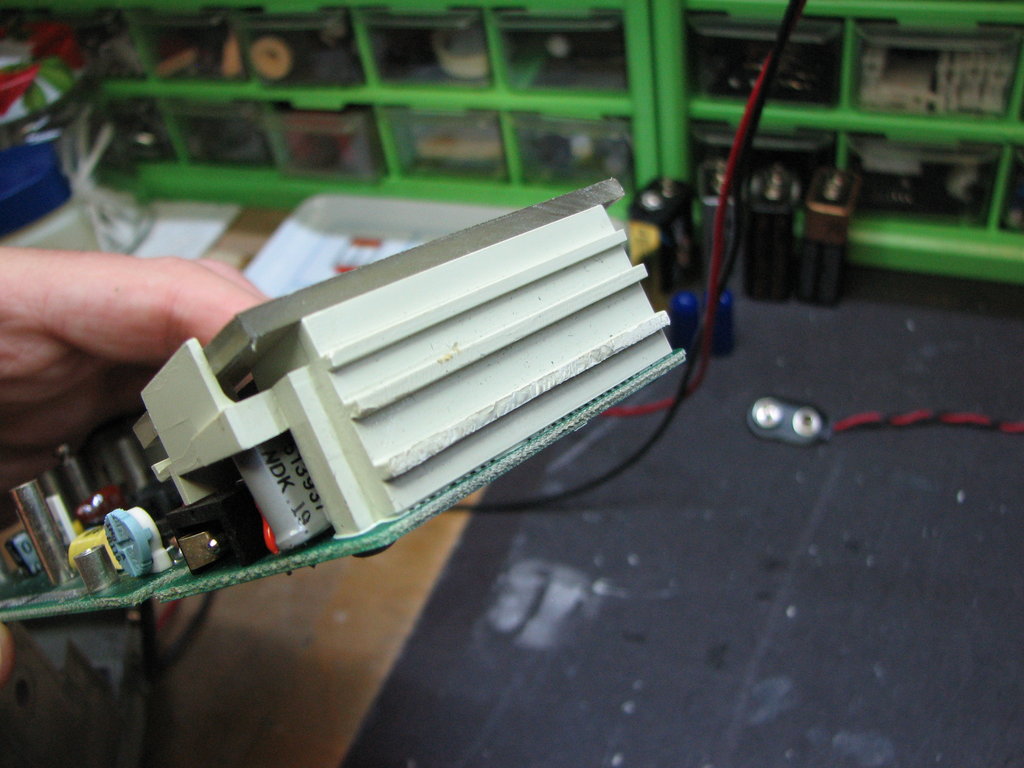
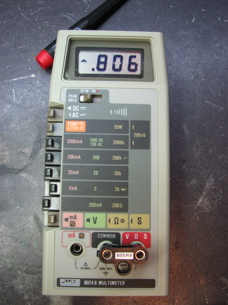
Fluke 8024B received 9-Oct-2013

as received
Nonsense readings.
Nonsense readings.
Solvent has welded the kickstand to the case.
Other than solvent, not too bad.
Signs of solvent damage to plastic in many places.
Some buttons look rough, must have been sanded.
Flexible connector damaged by solvent.
LCD support welded to case.
More solvent damage.
Where the LCD support was pried off.
Solvent has welded the LCD in place.
Leaky cap damage.
Two electrolytics total, both have leaked.
Cap leakage, not too bad.
Cleaned up.
Other electrolytic site cleaned up.
Not too good for a 22uF/16V cap.
That's not good either.  Both caps replaced.
Surprised the LCD works at all.
Main chip looks OK.
Remove U14 (quad CMOS switch) to decouple ADC input. It floats around as expected.
Shorting ADC input (black probe connected to COM jack) produces correct zero reading.
Injecting a 100mV DC signal straight into ADC.
The red probe has the 100mV signal on it. Excellent. ADC is working and by the looks of it, still calibrated.
Cut lead coming in from top board to isolate source of leakage current.
Negative offset of 0.33V appears on the input jacks. Fault is between here and the cut track.
After days of looking, found that one of the flex connector runs leaked on the order of 20 to 30 meg-ohms to the adjacent conductor.
On a whim, reversed the connector, hoping that the leakage wouldn't make as much difference at the new location.  It worked!
Ohms OK too.
Broken button.
Extreme button repair commencing.
Hole for switch stem filled up with putty and scrap plastic.
More scrap plastic for side mold.
JB Weld epoxy poured in.
Some shaping required.
Not too bad.
I could always use a manicure.
Peas in a pod.
At this angle, LCD is a bleedin' mess.
Looks reasonable from straight-on.
Not too bad for almost being destroyed by solvent.  Peak hold circuit a bit wonky though, needs work.

  • Recent Posts

    • IBM 8060A/AA (Fluke 8060A) Refurbish
    • Reality Check
    • A Very Unique Fluke 8060A
    • Fluke 80-series Jack Assembly Rebuild
    • Dirty Multimeter Clean-up
    • Fluke 70-series Knob Removal
  • Chatter

    • Hernandez on Beckman LCD Assembly Repair
    • Hernandez on Beckman LCD Assembly Repair
    • vince on Beckman Industrial HD140 Multimeter
    • vince on Beckman Industrial HD140 Multimeter
    • Ludwig Amann on Beckman 3020 DMM Repair
    • ludwig amann on Beckman 3020 DMM Repair
    • ludwig amann on Beckman 3020 DMM Repair
    • Jorge on A Very Unique Fluke 8060A
  • Tags

    • 70-series
    • 80-series
    • 170-series
    • Beckman
    • Corrosion
    • DMM
    • Fluke
    • HP/Agilent
    • LCD
    • Oscilloscope
    • Safety
    • Tektronix
    • Vintage
  • Categories

    • Gear
    • How-To
    • Miscellaneous
    • Modifications
    • Reader-contributed
    • Repair
    • Teardown
    • Theory
  • Archives

    • November 2016
    • May 2014
    • March 2014
    • January 2014
    • October 2013
    • September 2013
    • August 2013
    • July 2013
    • May 2013
    • April 2013
    • March 2013
    • February 2013
    • January 2013
    • December 2012
    • November 2012
  • Forums

    • EEVBlog Forum
    • Badcaps.net
    • diyAudio
    • Electro Tech Online
  • Helpful Vendors

    • VoltageStandard.com
    • ArtekManuals
    • Standards and Calibrations
    • QuadHands
    • Saelig Unique Electronics
  • More To Explore

    • KuzyaTech
    • Steve's Antique Technology
    • The War Planner
  • YouTube Channels

    • EEVBlog
    • Big Clive
    • w2aew
    • Scullcom Hobby Electronics
    • mikeselectricstuff
    • The Signal Path Blog
  • Email

    modemhead@mrmodemhead.com
  • Meta

    • Log in
    • Entries RSS
    • Comments RSS
    • WordPress.org
Mr. ModemHead
Proudly powered by WordPress.