
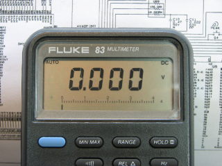
The Fluke 83 Multimeter is part of the 80-series that was introduced in the very late 80s. This unit is the lowest model in the line-up and has a basic DC accuracy of 0.3%. It does not have an RMS AC converter or a backlight like its venerable cousin, the model 87.
This example arrives without its usual yellow holster and is completely dead. No display at all. Inspection of the internals reveals no particular problems, except for the fact that someone has inserted the wrong fuse at the F1 location. This should be a BBS-1 fast-blow fuse, but a 1A time-delayed fuse has been installed instead.
Further disassembly reveals that one of the four plastic clips holding the LCD assembly to the main PCB is broken. These four clips are necessary to maintain even pressure on the elastomer connectors between the PCB and the LCD. A gentle squeeze with thumb and forefinger while the meter is turned on still reveals absolutely nothing on the display, so this is not the main problem. It could however, lead to problems later.


Touching an oscilloscope probe to both sides of the clock crystal reveals that there is no clock signal at all. Maybe there is a power problem. The service manual has a handy chart for the voltage levels on the board. The power supply for the meter is bipolar, meaning it has both positive and negative potentials with respect to the circuit ground. Vdd is the positive rail at 3.0V, and Vss is the negative rail at -3.2V. Circuit ground is referred to as ‘digital ground’ in the manual and is connected to the COM input jack.
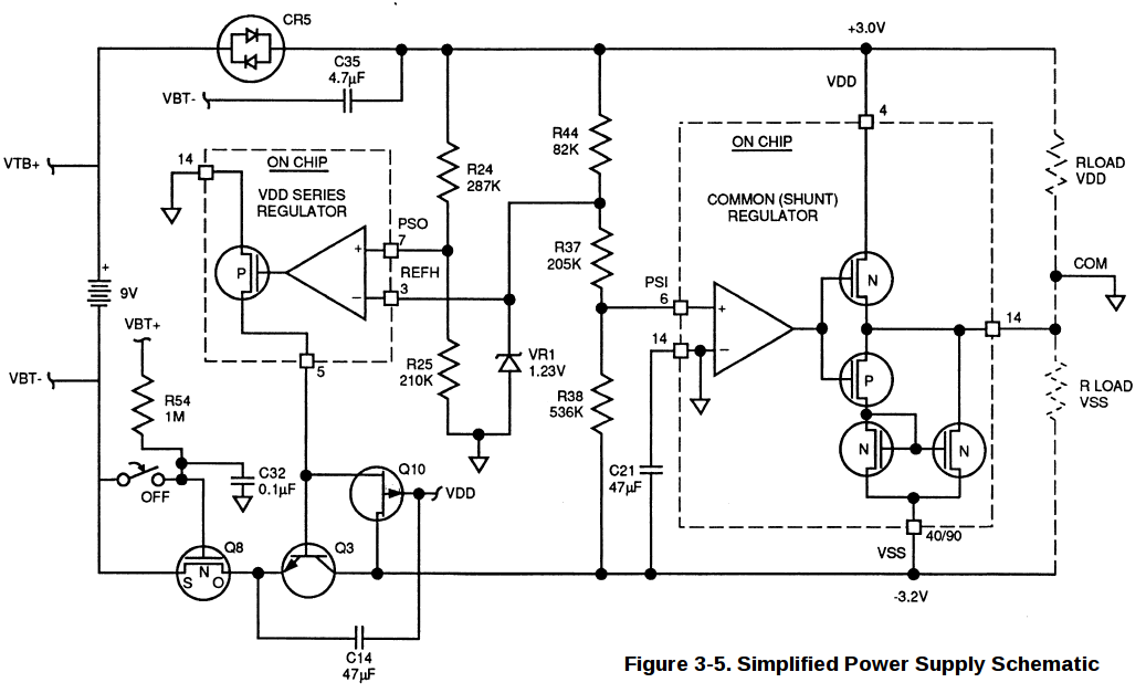
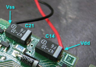
Inspection of the schematic reveals that the negative end of C21 is connected to Vss and the positive end of C14 is connected to Vdd. Both of these caps are 47μF and are relatively large, making for easy places to find and probe these voltage levels. The COM jack makes a convenient ground connection point. A DC power supply set at 9.0V is connected to the 9V battery clip of the meter. This insures that the full nominal input voltage is available for further measurements.
At this point, Vdd measures 2.35V, and Vss measures -0.07V with respect to ground (the COM jack.) Both of these numbers are approximate, because the readings are unstable and appear to drift up and down a bit. Not good at all, especially Vss. Let’s see what the service manual has to say about power supply trouble-shooting:
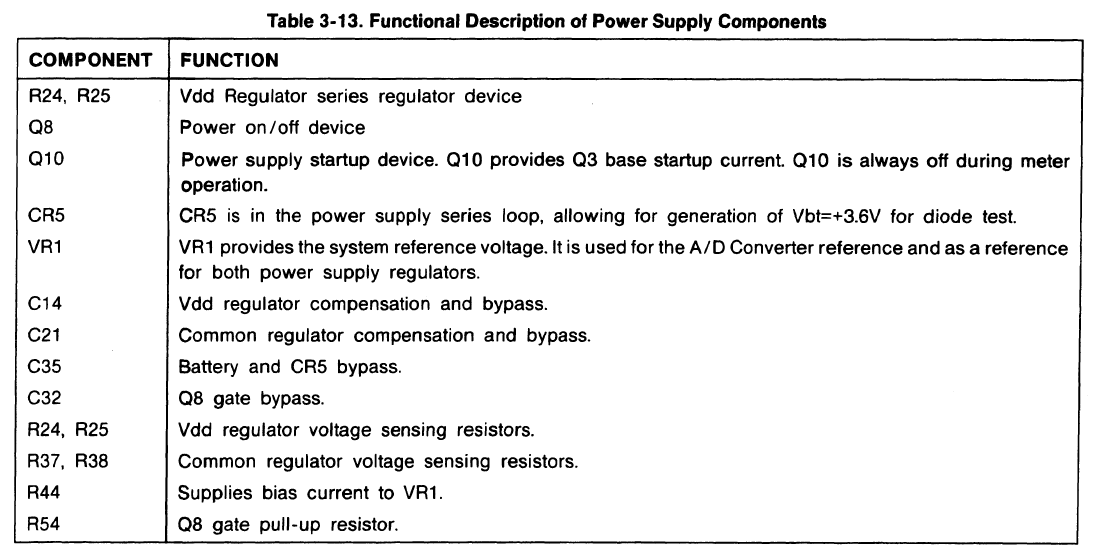
3-34. TROUBLESHOOTING – POWER SUPPLYThe two regulator circuits are interrelated; a malfunction in either the common regulator or the Vdd regulator may cause a problem in the other. Refer to Tables 3-13 and 3-14 for descriptions of power supply components and voltage levels, respectively. To isolate the problem regulator circuit, disconnect the battery, and drive Vdd – Vss = 6.2V with a power supply. This procedure tests the common regulator independently of the Vdd regulator.
 It appears that there are two different, inter-connected voltage regulator circuits, and we will have to isolate the problem to only one. To do this, an external DC power supply must be set to 6.2V and connected across Vdd(+) and Vss(-) , as instructed. This takes over the job of the Vdd regulator, and leaves the Common regulator free to do its thing (or fail to do its thing.)
I soldered two small wires to the cap leads identified earlier to facilitate this hook-up, and continued with the service manual instructions:
Now check for Vdgnd – Vss = -3.2 ± 0.3V. If this test is successful, the problem lies with the Vdd regulator; refer to Vdd Regulator Troubleshooting later in this section. If this test is not successful, the problem lies with the common regulator; continue with the Common Regulator Troubleshooting below.Vdgnd (and sometimes DGND) is the service manual’s nomenclature for ‘digital ground’, which is represented on the schematic as a ground symbol with a ‘D’ in it, and is connected to the COM input jack. Measuring between ground and Vss yields a reading of -0.33V. This is nowhere near the nominal -3.2V called for, so according to the manual the problem lies with the Common regulator circuit. Continuing with the procedure:
3-35. Common (Shunt) Regulator TroubleshootingTo troubleshoot the common regulator, connect the power supply so that Vdd, Vss, and DGND (digital ground) are supplied from an external power supply. This procedure over-drives the large on-chip shunt transistors; the bias current from the power supply ranges from 10 mA to 100mA. Refer to Figure 3-5 for a simplified diagram of the common regulator. Make the following tests:
 Now we’re directed to connect two external power supplies in such a way that it overrides both on-board regulators, in order to perform further tests. The manual tersely informs us of the expected currents to be drawn from the power supplies, so that must be important.
Using a dual power supply, I set supply #1 to 3.2V and connect its positive output to ground, and its negative lead to Vss, thus providing -3.2V for Vss. I set supply #2 to 3.0V and connect its negative lead to ground and its positive lead to Vdd, thus providing +3.0V for Vdd. Two multimeters set to current-measuring mode are inserted in series to monitor the ‘bias current’ of each of the two supplies.
1. Check for +1.235V ± 20mV (Vrefh) at the cathode of VR1. If Vrefh is not correct, check VR1, R19, R20, and R44 and the traces to these parts carefully. If Vrefh is still incorrect, U4 is bad.Vref measures 1.236V. Practically spot-on, so let’s continue with the next step:
2. If Vrefh is correct, measure the voltage at U4 pin 6 (PS1). If Vps1 is not equal to 0V ± 0.15V check R37 and R38 and their associated traces. If Vps1 is still at an incorrect voltage, U4 is bad.The voltage at U4 pin 6 (Vps1) is 0.011V. No problem, continue:
3. A DGND and Vss current much larger than 100mA may indicate a problem with Q12 (Vdgnd-to-Vss quick turn-off clamp) or its base drive signal from U6. The Q12 clamp is off when the instrument is on and on when the instrument is off.The current indicated by the multimeter I have in series with Vss indicates 133mA is being drawn. This is not good. The manual suggests Q12 as a possible problem. Checking the base-emitter voltage on Q12 shows it to be biased on. The collector is tied to ground, and the emitter is tied to Vss, so if it’s on, it will be essentially shorting ground to Vss. That would definitely cause a serious problem while the meter is supposed to be ON. Q12 is not supposed to be on when the meter is on, so let’s just temporarily remove it and see what happens.
 After removing Q12, the LCD assembly is replaced and the meter is connected to normal 9V power through the battery clip. It turns on, boots up, and measures a 5VDC reference voltage perfectly at 5.00V. That’s progress, but we don’t know why Q12 is on when it should be off. A check of its base-emitter and base-collector junctions show good readings on a DMM diode-check range, so the transistor itself is not the root cause.
 and Vss (negative supply).")


The base of Q12 is tied directly to the output of one of the inverters in a CMOS hex inverter package (U6). Note that U6 is powered directly by the battery voltages Vbt+ and Vbt-. (This is interesting, it means the chip is always powered on, regardless of the meter’s rotary switch position.) With Q12 removed, the voltage at pin 8 (inverter output) is 3.62V which is definitely a logic high. The voltage at pin 9 (inverter input) is -2.52V which is a logic low level.
To completely check the inverter operation, I temporarily connect a 10K resistor from Vbt+ to pin 9, to provide a logic high. The voltage at pin 8 goes to -5.18V, a logic low signal. That means the inverter is working correctly. So whatever drives the ‘PDS’ signal now becomes prime suspect. Something is pulling it ‘down’, making it a logic low level, when it shouldn’t be.
") The PDS signal originates from the ‘Code Switching’ portion of the schematic. There is a concentric circular arrangement of black-colored pads on the PCB behind the rotary switch, under a rotor carrying one pair of contacts that short across these pads as the switch rotates around. The black material is not metal, but is a conductive polymer thick film (PTF) deposition. This whole assembly is represented somewhat ambiguously on the schematic as S2.
The PDS signal originates from the ‘Code Switching’ portion of the schematic. There is a concentric circular arrangement of black-colored pads on the PCB behind the rotary switch, under a rotor carrying one pair of contacts that short across these pads as the switch rotates around. The black material is not metal, but is a conductive polymer thick film (PTF) deposition. This whole assembly is represented somewhat ambiguously on the schematic as S2.
It’s purpose is to provide the meter’s processor with a way of determining which measurement function has been selected by the rotary switch position.
If the processor raises AP6 to some known voltage, the resistors R65-R70 form a voltage divider stack with taps going to different pads on the switch. The voltage level on P03 will then indicate which position the switch is in. (This functionality can be tested in a ‘Rotary Switch Test’ initiated by holding the ‘Range’ button while powering up the meter.)
To complicate matters, there are ‘fingers’ in-between the pads that are connected to Vbt-. These will cause the sense line P03 to ‘blip’ down to Vbt- as the switch is rotated between functions, providing a signal to the processor that the knob position has changed. It is unclear from the diagram, but a close examination of the switch after gently popping the rotor off of the hub reveals that the PDS signal we’re interested in, is bridged across to this Vbt- trace when the switch is in the OFF position. It is unconnected when the switch is in any other position.
To summarize: when the switch is OFF, PDS is logic low, inverted to a logic high by U6, which turns on Q12, clamping Vss to ground. When the switch is in any ON position, PDS is pulled up to a logic high by R54/Vbt+, inverted to a logic low by U6, turning off Q12. Keep in mind that U6 and these logic levels are powered straight from the battery, and are unaffected by the meter being turned off via the rotary switch.
During all this close examination of the code switch in order to find out how it works, it has become clear what is the root cause of the problem. The switch has undergone some sort of abuse which has ground away some of the conductive black material, leaving a significant amount of it between the pads connected to PDS and Vbt-. The amount of current leakage through this material overrides the R54 pull-up resistor, keeping PDS at a logic low level even when the meter is turned on.

 on the underside of the PCB.")
 by conductive debris, causing the fault.")


A generous amount of IPA (isopropyl alcohol) and a toothbrush clears up the conductive debris problem. Examination of the rotor reveals nothing amiss which could have caused the problem in the first place. The conductive black areas on the PCB are somewhat damaged, but not enough to cause malfunction. The service manual calls for some obscure lubricant to be used here, but since I don’t have any, I am loathe to substitute anything that might be detrimental to the PTF material.
Q12 is re-installed and the LCD assembly clipped back on. The meter is powered up via its normal 9V battery connector. Vdd now measures 3.20V and Vss measures -3.20V. The Vdd measurement is a little high, but still within the ±0.3V tolerance. The meter draws only 0.78mA from it’s 9V supply in DCV mode. All functions and ranges operate properly, and to top it off, the meter is still well-calibrated. A Rotary Switch Test yields the values 0, -32, -64, -96, -128, -160, and -192, which are all nominal.
Success!


In this early generation of 80-series meters, the case has to be opened to replace the battery. Perhaps some careless user allowed foreign matter to become lodged in the switch. Also, there is the potential to engage the switch hub with the knob via its hexagonal shaft in such a way that it is not aligned properly. This would allow the switch hub to be rotated beyond where it normally stops. Some evidence of that can be seen in the previous gallery photo with the rotor removed.
Epilog: This entire troubleshooting procedure could have been avoided by a complete tear-down and visual inspection. The cause of the problem was hiding behind the code switch rotor, and was easily fixed by a simple IPA cleaning. But then we wouldn’t have learned how the ‘code switch’ works, and why the meter isn’t really off when it’s supposed to be turned off. (It draws 8.85μA with the selector in the OFF position.)
DMMCheck calibration check results for this Fluke 83:
| Reference | Reading | Notes | |
| DC | 5V | 5.00 | |
| 1mA | 1.00 | ||
| AC | 5V | 5.55 | nominal for non-TRMS |
| 1mA | 1.11 | nominal for non-TRMS | |
| Ohms | 100 | 100.0 | REL feature used |
| 1K | 1.001K | ||
| 10K | 10.01K | ||
| 100K | 99.9K | ||
I have a Fluke 83 III multimeter. Last time I turned it on, all LCDs would not stop blinking. Any idea what could be the cause?
Thanks.
David
That could be a lot of things. The simplest cause could be the battery. The 80-series will blink when the battery capacity is on the hairy edge. It powers the meter on, the voltage drops, the meter resets, and it goes into an endless loop.
I’m super late to the party on this one, but I just repaired a craigslist Fluke 83 and this is how I’d characterize the LCD function. Basically, the connection between the PCB and the elastomer towers on the LCD module degrades. You can pick up replacements on ebay, but I actually found that rubbing both sides down with IPA fixed the issue perfectly.
Yes, cleaning with IPA is job #1. Fixes all manner of ills.
I have a 83 v3, With a fresh battery 1st operation of rotary switch works fine, but once I switch it to off and back on again; all segments stay on regardless of position. I leave it off for a while and it works ok again till I turn it off.
Any idea what the problem could be?.
Great site!!
Can you answer a question for me?
disassembly of my Fluke 83 reveals that one of the four plastic clips holding the LCD assembly to the main PCB is broken. This causes intermittent problems with the display.
Can a replacement be obtained
Contact the Fluke parts dept. at 1-888-99-FLUKE. Ask for part #824516, which is the “top shield” for an 80-series meter. If they don’t have it available, I have seen them listed on eBay occasionally. The same part fits on an 83, 85 or 87. Search for “Fluke (frame,shield)”.
Thanks. The battery has been replaced and the meter is working properly again.
David
Excellent. Glad it was a simple problem.
I have a DMM with the same problem, haven’t opened it but if I find that the “PTF” is broken do you think I have any chance of fixing it?
No need to assume the worst, if you haven’t opened it up yet.
I have not yet run across an original 80-series in which the PTF material was damaged badly enough to need anything more than cleaning. But if I do, I have a small vial of Caig CaiKote 44 here which might work, but no guarantees of course.
I opened it and the contacts are actually copper or something similar, maybe zinc plated copper… Anyways the grease was hardened and dirty, cleaned it a bit with a cotton swab and now the multimeter works.
Thanks.
Glad to hear you fixed your multimeter.
Fluke switched to the metal contacts in the III generation, and did away with the rear set of contacts completely in the V generation.
As an engineering student, who was interested in repairing and troubleshooting electronics, I’m really impressed by your work. The care and attention that you’re putting into the restoration of these devices is rare nowadays.
Thank you for this page and the detailed tutorials!
Thanks for your kind comments.
I have a vps410 is two year old , only I manipulate with care
when try to calibrate turn plastic cover to access to variable capacitor trimming
the probe leave continuity. Its very expensive do you know how disassemble the probe by side of scope
thank for answer
Hi there;
Im having a problem on my FLUKE 85
on the screen show the battery icon so I change new one nil help,
and even the selector is in off position the meter still on
on the LCD indicated OL.
thanks
I have a Fluke 718 pressure calibrator indicating OL message. Long time no used.
Please help.
Many thanks
I’m sorry I have no experience with that device.
Hi, I ‘m from Mexico , The problem I have is with a fluke 87 lll . This will not finish booting and flashes continuously. I’ve changed the battery , without solving the proble . Can you help me. Regards.
From afar, all I can give is general advice: Disassemble and clean the circuit board with isopropyl alcohol. Particularly the rotary switch contacts on the back side. Visually inspect the board for signs of damage from battery leakage.
Just wanted to quickly share my fluke 77 fix. Display seemed stuck in p.o.s.t. ie all lit up and just stayed that way. After cleaning the mf switch with d5 and static testing all I could, was at a loss. Your website encouraged me to have another try. I cleaned the lcd connector with isp, no help, but got me back in the thing and thinking. I shorted crystal momentarily with probe tip and display turned off.. okay, must be running. I reflowed both “postage stamp” chips with flux and very small amount of solder, just enough to keep tip wet and presto! Wish I had forethought enough to do them one at a time! Thanks for being such a meter geek 😀 . Oh yeah, broke cap behind battery clean off, fixed its stubby legs to some trimmed up ribbon wire long enough so it fit under that little plastic cowling… so happy my old faithful is back in service!
Great job on the repair and thanks for the comments. I learned from another DMM aficionado that Fluke had a run of 70-series units with faulty soldering on the analog chip (U1, the one closer to the input jacks.) I’ve only run into one like that myself, and it was a 75-II. It took me two tries at resoldering U1 to get it going. Still working, though!
I know this is an old thread but your tip about reflowing the leads on the analog chip resurrected one of my 77s from the not working but not throwing it away either pile. I am definitely adding this forum to my favorites. Now to dive into a box of discarded Flukes at work. Thanks for the great info.
Hi,
My fluke 83 started very slowly- about 5-7 seconds. А few years ago i checked all conections and many components, and came to the conclusion – problem with PDS signal. He needs several seconds, to change the level from 0 to 1 for starting.
Any idea?
R54 is the pull-up resistor for PDS and comes straight from the positive battery line. 1 Meg is weak, so it wouldn’t take much to drag it down. Q8 mosfet gate, U6P9 and C32 are all connected. If the meter eventually switches on, then Q8 must be OK, the rest are suspect. Also PCB contamination, dry or cracked solder joints, and of course the code switch contacts. Resist the urge to make R54 smaller, it connects across the battery while the unit is off. 9 uA leakage is not so bad, but any more might flatten the battery.
I test with R54= 0.5M, but without success. Contacts are clean. Never mind, maybe problem is in Q8 becouse is not original .
And this is another solution with LCD screen problem. Resolder all pads with about 0.5mm thickness .
http://i055.radikal.ru/1502/6c/8cbe29c8702c.jpg
Hi
I got a 87 totally dead after get electrical arc generated from a high voltage power supply (up to 50 Kilovolts) The fuses are still good. Would you please give a recommendation where to begin with?
Thanks!
Totally dead does not sound good. The best (most repairable) thing that can happen for an over-voltage event is for the fusible resistor (R1) to fail open and/or the MOVs to fail short. But neither one of those failures should cause the meter to appear dead. So disassemble everything and inspect the board closely with some kind of magnification. Look for burnt tracks, and carbonized areas. Remember that carbon conducts!
Next order of business would be to obtain the service manual for the original 80 series models. Then like with any other gear, start by checking the power supplies.
I have a Fluke 85 (10 years old if not more) that quit on us at work the other day. With a replacement for the shop coming, I wanted to get this thing working for myself.
On ohms, it displays -330k where it should be OL, but does drop to zero with leads crossed. On DC volts, it shows -0.320V at rest, and -17.0V measuring a 9V battery.
Battery within the unit was changed. No dice.
Any words of wisdom before I dig into the service manual you posted?
Those symptoms sound like a classic case of PCB contamination. Disassemble carefully (watch those fragile clips and tabs!) and clean/brush the PCB with the strongest IPA you can find (91% or better). Mind the adjustment trimmers, but otherwise it’s OK and preferable to just dunk it. Allow the board to dry at least an hour in front of a fan before re-assembling. A few shots of compressed air can help coax IPA out from under the chips, and inside the jack assembly, where it could set off the lead alarm (no big deal, it’ll dry up eventually.)
In this case I would pay particular attention to fine-pitch leads on chips like the large ASIC under the LCD (U4). Drag something sharp like a toothpick between each of the leads, I’ve seen unidentified “gunk” collect there if the meter was used in a dirty environment, and it will manifest with symptoms just like what you describe.
Thanks for responding!
Ok. Dug into this a bit deeper. First off, I removed the back half of the rotary switch, and cleaned the black conductive surface with IPA, as well as the conductive fingers on the cover. It was fairly filthy, so I was hopeful this was it. Nope, same symptoms. The front of the switch is a wafer assembly with contacts on both side. I carefully cleaned the front as best I could with IPA and a toothpick on the traces, but there is essentially no access to the back contacts without desolating the entire wafer, which I hope to avoid. No fix.
Performing the rotary switch test results in the following: 00, -34, -66, -98, -130, -163, and -192. These are all a couple digits high, save for 00 and 192. What are your thoughts on this? I don’t think these are digital, so would a couple off cause my issues?
Finally, I went through the voltage table checking the power supply voltages listed and got the following:
VDD 2.965
VSS -3.202
VBT+ 3.577
VBT- -5.302 (new batt)
REFH 1.236
PS0 1.255
PS1 0.004
I couldn’t figure out how to test the last 3 items, but I think I can safely say the power supply is healthy. So that leaves me with 2 thoughts. The switching is still causing the problem, or I have another unrelated and undiscovered issue.
What are your thoughts on how to proceed?
Thanks!
It is unlikely that either switch can cause the symptoms you described. The rotary switch test results are fine and only indicates that the voltage divider on the back side is working, which is the method by which the processor determines the switch position.
My recommendations are to go back and read my previous reply.
Hello,
I have a Fluke 83III. The screen displays in each position of the rotary switch, the top AUTO, right above the other m and 400 mV. The display in the center will alternate between numbers and OL. When you turn all characters are displayed.
Can you help me where can be broken?
No I can’t say what’s wrong, but do begin with the simple stuff first. Try a fresh battery of course. Carefully disassemble the unit and inspect, while minding the fragile clips and tabs. Clean the switches on both sides of the board. Use a magnifier, and look for damage to the circuit board from battery leakage, humidity and so forth. Circuit board damage and/or contamination is a common DMM problem.
My Fluke 87 is quite old, but not used often. After using it today (normal functions, no low-battery indication), after I shut it off, I noticed it ‘ticking’ (like the power up ticks) and the back lights flashing, both intermittently. I replaced the battery. I noticed a piece of foam, glued to the case, apparently to keep the battery from rattling around. That’s a bad choice. That black foam should be avoided like the plague, for any electronic application. It disintegrates. Could this stuff have gotten into the rotary switch? I’m handy enough, but I don’t want to disassemble it unless I have to.
Best,
I connected my Fluke 83 III to a voltage supply in excess of the meter’s limits. The gap capacitor burned up. I replaced the gap capacitor however when measuring resistance the meter jumps around a bit around 2M ohms.
Well, thanks for the input. I’ve been using the Fluke ever since. To wipe the slate clean, I just press the speaker button and the DMM resets to 0.00. (when the dial is in the ohms setting).
I loaned my Fluke 83 III to a friend. Well, he tried to measure the voltage on a microwave transformer. Needless to say I have a nice grey and yellow brick now. I opened it up and found a 3.5K resistor right off of the + lead input that took the brunt of the blow. Has anyone experience with this kind of damage, is the unit toast or is there hope.
If the unit still boots up and displays some numbers, there is definitely a chance it is repairable. The “front end” of these units have several (possibly sacrificial) components that are designed to dissipate the energy of an overload situation. The 3.5K wire-wound resistor is one of them. There are also some varistors (MOVs) and a PTC thermistor. These parts are usually replaceable. Of course it is also possible the surge destroyed something for which there is no off-the-shelf substitute, which would make repair very difficult.
If you need trouble-shooting advice, I might suggest starting a topic at the EEVBlog Repair Forum, with clear focused pictures of the circuit board top and bottom.
Side note: Never loan the “good stuff” to friends. Harbor Freight cheapies are good for that. 😀
Thanks for replying so quickly. Unfortunately the unit appears dead, no digits in LCD. Must have been one heck of a transformer eh? looks like I have a brick now.
MOTs are not to be trifled with. Think about it, 1100 watts at several thousand volts.
No display generally means the processor isn’t running because it’s dead or has no power supply. It might still be repairable of course, but some serious trouble-shooting will be req’d to make the final call. I’d say your friend owes you a new 87-V for Christmas. 🙂
I have a fluke 87 and it just recently started not measuring AC volts and it starts climbing up slowly but doesnt measure correctly the DC voltages.Im not sure about any other task that may not be correct, but I know the continuity is fine. What could be its problem
My screen housing has 2 broken clips (85 III) where can you buy the housing the for that screen? mine works fine but now the screen flickers in and out.
I have a 83 meter, every thing is good but resistor measure function is not working, it keeps no response or getting big number when two probes short together. Any reason will cause it? Thanks.
There could be many reasons, maybe one of the front end components? If voltage measurement is working, the 1K fusible resistor is probably ok, but check the 909K resistor right beside it, which is in the ohms sense line. Also check the PTC thermistor, should be around 1.5K. Other trouble-shooting tips: use another meter to check the open-circuit voltage and short-circuit current on the 83’s input jacks in ohms mode. Also download a copy of the 80-series service manual, check the last few pages for a nice diagram of “Ohms signal flow”, with all the relevant components highlighted.
I have 28II fluke Multimeter , I have replaced the rotary switch , in this case after fixing the rotary switch every two rotation only the parameter is changing , could anybody advise the solution for this.
I’m sorry I have no experience at all with this model, and I can’t say that I fully understand your problem. Best advice is to check, double-check and triple-check your repairs, solder joints, etc.
I have a question about 83V, I have EEPR ERR on the display when I turn it on, is there a way to reprogram the eeprom to fix the problem. Or maybe somebody has a eeprom image in some kind of repository I can use…
I have another 83V that works perfectly fine, so, I have a potential donor, any experience with fixing trouble like this.
I’m not too familiar with the details of the newer models, so I’m no help. I think that error probably indicates the calibration data has been lost.
I have a fluke 83 with a cracked lcd, I cannot find one anywhere since they are discontinued and im wondering if the other 80 series lcds will work with this one?
The 83 and 85 models use a common LCD. The 87 LCD looks the same but has a different pin-out. I put an 87-III LCD in my original 87 and it works. From that I would guess the 83/85-III LCD is compatible with the 83/85 models. The series V model LCDs are not compatible at all because of the change from 4000 to 6000 counts.
Great site love the details and the troubleshooting.
Could you indicate where I could get the complete housing for a Fluke 83 III. A friend gave me a working meter but the gray housing is cracked/broken in some places.
Best regards,
Allan .C
My Fluke 83 drains its battery when not in use in a couple of weeks. When the rotary switch is “Off” it draws 7.2 micro amps. The meter you repaired also draws current when “Off”. Is this normal, or is it causing the battery to go flat?
I cleaned the meter and switch area with Contact Cleaner before I read your description. Should I clean it again with IPA?
A number of your followers ask about broken tabs that hold the inner casing together; I successfully repaired mine with Q-Bond. Basically superglue and a filler powder; great stuff.
Thank you for your web site, great service, much appreciated.
There is a 1 meg pull-up resistor (R54) that ends up connected across Vbat+ and Vbat- when the meter is switched off. For a fresh 9V battery this results in a current of 9uA, less for an older battery of course. This level of current would take over 6 yrs to flatten a typical 500mAh 9V battery. Not a problem.
Thanks for the Q-Bond suggestion. I’ve never heard of this product but from Amazon reviews it sounds like it should be in every repairer’s toolbox.
Edit: I think I missed your first sentence… If this is happening but the current draw measured is only 7uA, then the battery-flattening current isn’t going into the meter.
Thank you Modemhead, I will try cleaning the switch again with IPA and a soft toothbrush and see if that fixes it. Is there any other possible malfunction that could cause loss of battery life?
I find it hard to believe it’s flattening the battery while not in use if you measured only 7.2 uA current draw with switch OFF. Check the current draw while it is ON as well to see if that looks normal (should be around 1mA or so.)
Not that I’ve seen every possible fault by any means, but the “code switch” does seem to be the prime cause if the meter will not turn off properly, or draws too much current with the switch OFF.
How did you fix the broken plastic clip. I have the same problem here and I cant find a replacement part. Any ideas on a part number or where I can find the plastic part with the clips.
Just wanted to say thanks for all the great information and pass along a bit of hard won knowledge in case anyone finds themselves in a similar situation.
I took apart my trusty Fluke 87 (vintage 1991) to see if cleaning the carbon switch would fix the occasional turn-on while in the off position.
Got it all cleaned up and re-assembled only to find things had gone sideways. AC volts seemed OK, but DC volts, millivolts and ohms were whacked (volts were ~ 3.5v, mV were ~ 350mV, ohms were negative all with no leads connected). I ended up going through the whole repair process above to find nothing wrong.
Long story somewhat shorter, I had somehow managed to get the top and bottom rotary switches 180 degrees out of sync. I’m just glad I didn’t connect it to anything, I have no idea how signals would have been (improperly) routed and possibly caused real damage.
Now I need to check out that Q-Bond stuff, I broke two snaps in all the fun.
And FWIW – It does look like cleaning the carbon switch has helped.
Just confirming that Q-Bond fixed both snaps. Amazing stuff.
Hello,
First of all…thanks Mr. modemhead for starting this “blog site”. Just great!!
After reading the commends my Fluke 83III is running again!! cleaning with IPA and a new top shield part 824516 and Q7. Thanks!!
Fred from the Netherlands.
I have a Fluke 87 (original version) which seems to work OK, but the Rotary Switch Test gives the following numbers: 0, -29, -62, -95, -126, -159 and -192. Two are right on the money and the rest are pretty close. What is the allowable tolerance for this test?
Great site . . . thanks, Warren
The tolerance is +/- 12, so your test passes.
Ever have to repair the PTF under the range selector? I’m wondering what to use…
I’ve got an 87-3 where the meter still works – albeit a little wonkily – but the range test fails on the first switch detent (AC position) and anything after the DC range is correct. The traces under the rear rotor have somewhat decomposed from a nasty contaminant and I was considering using conductive paint to “repair” them. Not sure if it’ll work but I couldn’t find another product to try.
Yes, I repaired an 87 in which the PTF looked okay, but the voltage divider didn’t work because the resistance between positions somehow became unequal. Fixed it with this: MG Chemicals Carbon Conductive Pen.
That’s great, I saw some not-so-great reviews for the MG pens and lost confidence… but now I’ll give it a try. Thanks!
After I posted the previous comment, I realized that I should point out that I did not have to repair the PTF that comes into contact with the rotor. If you have to repair a section directly under the wiper, then I don’t know how well the carbon ink would hold up when the contacts are dragging across it.
Hi, I have a fluke 83 with unstable measurement. At mean, the reading start with high values and decrease during the time. Calibrate is impossibe because the resistors are out the rangeand the unstable readings. The Vdd and Vss are okay.
Do you why this problem may be occurs?and how to solve this?
Remove the rear shield and LCD assembly. Be careful not to break the clips. Immerse the board in strong isopropyl alcohol (IPA, 91% or better) and use a brush to clean the board. Allow to dry thoroughly, preferrably with a fan and/or mild heat.
This may seem like a low-tech solution, but the majority of the time, the symptoms you describe are caused by tiny leakage currents in the high-impedance section of the circuitry.
Thank you it is was very helpful to me.
I have another question with another fluke 83. The fluke has a problem with ac voltage in high voltage and “high” frequency. The fluke is blink and beep and finally turn it’self off(of curse, it doesn’t measuremts well). This phenomena occurs in voltage of 650v in frequency of 900hz or higher(in voltage of 1000v it’s appears from 200hz and higher). Any other function of this fluke is fine, do you know the problem?
Wow that’s a weird one. I have no idea what could cause that. I don’t usually work with high-frequency voltages that high.
Thank you for taking the time to document and to post your repairs! Your site is a great resource for keeping these great meters going. I am researching for switch lubricant options and am testing some silicone based grease (in very small amount) on some cheap meters that get used daly.
At my work place we use this non reacting grease that is safe for gaskets and plastics called Fomblin (PFPE fluorinated lubricant). It does not evaporate or separate in my experience, even old long expired tubes of the stuff. We buy it from watchmaking equipment suppliers like Bergeon or Beko. Krytox I see as another brand of lubricants that seem to have similar stuff. Have you tried any lubricants that work well?
Thank you for your kind comments about the website.
Lubrication depends on having a thin film between the sliding parts, which I find complete contradictory to the concept of electrical contact. Any lubricant you put there must be displaced by the pressure of the contacts. So I prefer to leave the electrical contact part of switches clean and dry. Hubs, detents, and other moving pieces I just use some basic silicone grease in very sparing quantities since that stuff creeps and creeps and creeps.
Hello… Are you still fixing the 83’s? Mine works perfect but refuses to display a value when trying to measure a capacitor.. It “sees” that I am touching the leads and it auto ranges but it won’t display a value… Any ideas?
The capacitor is higher than 5uF? The original 8x series and the 8x-III meters only measure up to 5uF.
Hello, Nice to find your very great website
I have a 87III.
AVC=reading normal
DVC=0000
mV =0000
Ohm=OL
Diode=0000
Do you have any clue about this problem?
Thank you very much.
Hello dear Modemhead,
I have a fluke 83 with a problem in ohm and capcitor measurement functions.
In the ohm function the measurement show much lower than the actual value and the capcitor function show always OL.
The 9.996Mohm resistor is fine.
The other functions work well.
Do you have any idea what is the problem?
Any way to diagnose it?
Hi I have just got a fluke 83 III and just opened it as the fuses are both missing on inspection I noticed a component that looks similar to polypropylene cap that looks damaged on the right-hand side of the bottom fuse just above 2 resistors when I came to your site I see your faulty one is the same it is designated as K11 in the service manual layout could you confirm if you know what this component is and its value so I may replace it. Many thanks Mark.
Hi, my Fluke 83 multimeter does not power up, I put a new battery in and nothing happens. Is this fixable?
Thanks
Hi, I believe this is the multimeter I sold, I do repair things and even checked the rotary switch-obviously not well enough! anyway big well done, it just shows that a bit of patience in repair does pay off!.
Hi,
I have a Fluke 85 dmm. I am seeing AC functionality not working. When in VAC mode, I always see 0V. But rest of the functions work for this DMM. I am thinking the only new block in the path is C1 cap. I am not sure if the AC buffer or any other block can cause the issue. Would appreciate any suggestion
I have a Fluke 83 multimeter. The last time I turned it on Ohm range as soon as I joined the test leads all the LCDs would not stop flashing. On the vdc range, -.354 appears on the display.
Nothing works correctly and no measures are possible.
The battery is 9.3v Vss -3.2 Vdd +3.2 Vref +1.22.
Can someone help me? Thanks in advance to those who will answer.
Hi: I have a Fluke 78 Stopped working, checked fuses, new battery still no function. I am a mechanic not a tech. Would like to send it to someone who could repair it. Do you do that? or recommendation. Thanks
Hi! Great website on pointers for repairs.
I have a Fluke 87 that had faded display and now totally no display.
I’ve checked all the voltages and they are within specs. I’v also probed the display pads, and most of the 31Hz LCD patterns are coming out, including the backplane signals. The elastomers and polarisers have also been changed, and the LCD does show some segments when removed and biased with some voltage ( around 2V).
Any ideas what else I could check?
Thanking you in advance!
I have a fluke 83 that will not read voltage or ohms. When you set to ohms you get the OL display and the beeper is continuous. Voltage reads 0 or random. I cleaned everything you mentioned. The fuses have continuity but still reads 0 voltage or 1 volt when testing 120. Any suggestions?
Thanks
jk
Try checking the fusible resistor.
Hi, I have a FLUKE 83 III that works correctly, but the LCD Display is already showing aging, it has a dark spot or shadow in the center, QUESTION: where can I get the correct Display for that model and what would be the reference number correct, the part number?
Thanks a lot.
Hi..
I brought several fluke items
From ebay. All are battery ruined out and corroded.
I believe that can be repaired. But i dnt have schematic of them
If you can help me to find out
Fluke 726
Fluke 62
Fluke 700G series
Thanking you
Hi,
i got a Problem with my Fluke 87-1. When i turn it on, it just beeps an the display stays on V AC. No matter what i select on the rotary switch.
Your guide already helped me understand the workings behind the mode selecting. All my values for the power supply section of it are correct, except for AP6. When the meter is turned on, it reads -2.8V.
U6 and Q12 are working like they should.
I already cleaned the rotary switch and the whole board with IPA. The ptf section seems to be in good condition.
Could you help out?
Greetings
It fails the rotary switch test (0000 in every position and crashes at the A positions).
P03 starts at 0V in the OFF and V AC position and then goes down to -2.8V in about -0.45V increments with every switch position. Between the switch positions it blips down to -4.4V (Vbt- is -5.35V).
May that be a indicator of the problem?
I have a fluke 83 and both the positive and negative wires from the battery broke off of the main board. Where can I find out where I need to resolder them?
I got a fluke 83 can I send to you to be fixed? Sceeen was coming on and off and now nothing.
Have an old broken 87 which doesn’t turn on, zero current draw. History unknown, may be I am not the first in.
Following your excellent repair guide, I have showed the Q12 stands driven when it shouldn’t be, and shorts Vss. Pin 9 of the CD4069 reads 146R to Vbat- , independent of switch position. Suspect the IC is kaput, but can anything else cause this? I don’t have hot air, and have to order the replacement IC, so hesitating to pull it. Thanks for advice.
Well, I removed the CD4069UB (and lifted just one pad!), but pin 9 still shows 176R to Vbat-. Much scrubbing the PTF switch area with 99% isopropyl did nothing. Interestingly, heating by hair dryer did not have any effect. The inverter itself tests fine.
Service manual’s schematic confuses much, but does not reveal what path pin 9 takes to leak to Vbat-.
I have yet to understand how the power up takes place, what with some of the clumsiest circuitry to accomplish that.
Hi , I have an old fluke 83v recently it flattens its pp3 9v battery in a couple of hours even when in the off position and seems to draw 1ma when in the off switch position, any ideas what i need to check ? 73 Paul.