
[Updated June 2013, see end of article.]
[Also see: newer article on IBM 8060A/AA Refurb]
The Fluke 8060A is another early-80s vintage handheld DMM. With a 4½ digit 20,000-count display, RMS-responding AC bandwidth to 100kHz, and direct readout in dB, it is still in use today and a favorite of those working with audio gear.
 This eBay acquisition was described as “powers up, but I can’t test it.” I assumed it would be non-functional, and when it arrived, that suspicion was confirmed. The display flickers, is sometimes very faint, but mostly shows a fixed arbitrary number, regardless of what function or range is selected. It is also in sad cosmetic shape, being very dirty and grimy. Repairs will be required to get this unit working again.
Disturbingly, the area around the buttons shows rust-colored deposits, looking as if there has been some water intrusion.


After opening the unit up, the internals do not look as bad as the outside. The components all seem to be in good shape, with only a slight layer of dust. The bottom of the PCB looks pretty good, no obvious signs of damage, missing parts, or any previous repair attempts.
The LCD assembly contains a daughter board with a QFP surface-mount microprocessor under the display. Hidden under this is a 40-pin DIP analog processor on the main board, in a nice purple ceramic package with gold-plated pins. Fluke calls this the Measurement Acquisition Chip (MAC). But I usually refer to this as the analog processor or AP chip throughout this document. [The official name is MAC, so I’ve standardized to avoid confusion.] Most of the parts have 1982 date codes, confirming the vintage of this unit.


The case parts and buttons get a good scrubbing with a strong solution of basic household cleaner. A rag, a toothbrush, and a little muscle removes most of the grime. The clean-up efforts make a marked improvement in the appearance. Other than a previous owner’s name engraved in the top side, there are only a few minor permanent dings and scratches, so the make-over is successful.


The switch assemblies make it hard to fully clean the circuit board with IPA (isopropyl alcohol), which is usually step #1 in any restoration project. So after the shield is removed, the accessible areas are dusted and given a cursory cleaning. The microprocessor daughter board has two elastomeric connectors, one for the LCD, and one back to the main board. Cleaning these improved the look of the LCD segments, but did not otherwise improve the functionality.
The Fluke manual for this multimeter is downloadable from Fluke’s manual archive and contains full schematics and service information. There are two versions of the manual available (1000V and 300V), and unfortunately neither one seems to include the serial number of my unit. A little research indicates that Fluke manufactured and sold this model well into the 90s, and these service manuals likely refer to the later revisions. The 1000V version refers to the lowest serial numbers, and going through it reveals a few minor differences, but it seems mostly accurate. The chief difference is the addition of an RMS converter sub-assembly. My unit does not have that sub-assembly, having instead a 14-pin DIP RMS converter directly on the main PCB.

Fig. 1 – Test Point Descriptions
In the absence of more specific clues, the best place to start trouble-shooting for just about any equipment is usually the power supply. The service manual has a list of test points, including those for the power supply.
TP1, the +5.2V supply measures 4.96V, which is outside the ±0.12V range specified in the manual. Close, but not quite right. TP2, the negative power supply rail measures -0.89V, but is supposed to be -5.1V. Obviously this is a serious problem, so let’s tackle that first. Looking at the schematic, we can see that an 8-pin DIP ICL7660 voltage converter IC (U4) is responsible for creating this supply, using an external 10μF charge pump capacitor (C21). The output of this device (pin 5) is connected to TP2 through a 12Ω resistor (R35) and goes on to provide the negative supply for the analog processor (Vss).

Fig. 2 – Negative Supply Generator
Examining C21 closely reveals a rather dull crusty-looking solder joint on the bottom side of the PCB, which is indicative of the capacitor having leaked corrosive electrolyte at some point. When removed, it’s obvious the cap has spewed its juice. It has an ESR of 69Ω, and actual capacitance measures 4.5μF. Both measurements are not good, and at this point, this cap appears to be the cause of the faulty negative supply.
After finding the first cap that has leaked electrolyte, all other electrolytic caps are automatically suspect. Visual inspection reveals that two other capacitors have leaked significantly. This includes C1 and C12, both of which are very near the 40-pin socket for the MAC chip. Lifting the device part of the way out reveals significant corrosion has wicked its way up some of the socket pins. All other capacitors look and measure OK, but a complete re-cap will be in order.
Removing the MAC chip completely reveals the extent of the damage. Pin 32 near C12 has weakened to the point of failure, as one side has broken completely off. Pin 21 near C1 is cracked and will no longer make contact with the chip leg. The socket will definitely have to be replaced, but waiting on a parts order puts quite a drag on the trouble-shooting process, so the socket gets scrubbed thoroughly with IPA and is allowed to dry. A slight outward bend on pins 21 and 32 will hopefully provide enough contact for further testing.


The bad capacitors are temporarily replaced with whatever’s on hand and the analog processor is carefully re-inserted into the dubious socket for further testing. Part of its function is regulation of the 5.2V positive supply rail, which is now looking good at 5.16V (TP1). The bad caps and corrosion on the socket contacts probably caused the original low voltage reading here. Unfortunately, the negative supply is still only managing about -1.1V on TP2.
Across the ICL7660 output is a reservoir capacitor (C23) that is integral to the charge pump operation. Even though it measured OK, it gets replaced. Doesn’t help, however.
I removed the ICL7660 and tested it on a breadboard with a DC power supply providing a 5.2V positive supply. It still only outputs -1.1V, so it is definitely bad. Maybe it was damaged by the nearby leaking charge pump cap. A new 7660, a new 40-pin socket, and enough capacitors to re-do the entire board are placed on order. Now waiting for the postman…


A small DigiKey box has arrived in the mail, so back to work. The new 7660 chip is tested in the same breadboard setup as before, and it definitely generates a negative supply voltage like it should. Confidence is high.
The new 7660 is soldered in. And after much careful de-soldering work with a solder-sucker and some wick, the old corroded 40-pin DIP socket is removed. The 4-layer PCB is somewhat difficult to work with, but fortunately it is quite sturdy. No pads or traces were damaged in this process. The new socket goes in easily. It has machined pin contacts, and should be much better than the old one.
A number of pins on the MAC are very high-impedance inputs, as evidenced by the guard traces around some. Soldering flux residue has to be cleaned, so that no current leakage paths are created.


The MAC is now settled in its new socket and all the suspect capacitors have been replaced with good-quality Nichicons. All major DC test points are now within acceptable limits.
| Test Point | Nominal | Measures |
| TP1 | 5.20V | 5.16V |
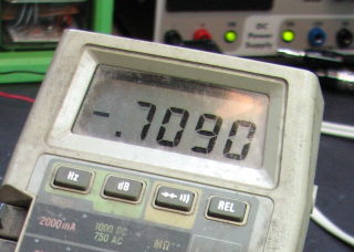
| TP2 | -5.10V | -5.09V |
| TP3 | 3.15V | 3.12V |
| TP4 | 1.2345V | 1.236V |
The meter boots up and passes its self-test! The LCD segments are solid. All functions seem to basically work. But with no input, or even a shorted input, the display never seems to rest at or near zero, like it should. A test input of 1.9V DC in the 2V range shows a pretty good reading. But higher ranges are considerably worse. Resistance measurements are 10% or more off. Something is not right.
With open inputs the 8060A will eventually settle on a reading of around -0.0150, sometimes more, sometimes less. This is not good. Another multimeter bridged across the input jacks seems to load this offset down some and bring the reading closer to zero. Interestingly, the other meter reads essentially the same as the 8060A. All this suggests the fault is a real, measurable (but tiny) offset current flowing somewhere it shouldn’t be, and not some digital counting error. But where?

Fig. 3 – A/D Input
R20 is a 220KΩ resistor that provides the sole path to couple the input voltage divider section into the analog-to-digital (A/D) converter inside the MAC (pins 6 and 7). Removing it decouples the entire front end from the MAC. While it’s out, an inspection reveals that the electrolyte leakage from the charge pump capacitor had some effect on one of the leads of this resistor, but not enough to cause a problem.
The front end is essentially a passive voltage divider configured by the range switches, and can be tested by injecting a voltage into the front panel jacks and measuring the result on the upstream side of R20’s location. This is done with the meter powered off, and is possible because this meter is manual-ranging. The divider is configured solely by the switches, and not by a microcontroller.

Fig. 4 – Voltage Input Divider Ratio Table
The divide ratios for each of the 5 DCV ranges are shown in this table from the service manual. So for example, setting the range to 20V and injecting 10.00V, the result is 0.100V because the divide ratio is 1/100 on the 20VDC range. Checking all the ranges reveals that the divider is spot-on, and probably is not the cause of any error.


 couples the input voltage divider section to the A/D inputs on the AP. It was affected, but not destroyed, by electrolyte leakage.")
In retrospect, the previous exercise was mostly unnecessary because of two things:
- The residual offset voltage measured at the 8060A’s input jacks by another DMM (with the 8060A powered on) disappeared when R20 was removed. The current producing the offset was coming from the MAC side of R20.
- The residual offset voltage was negative. Pulling the positive input terminal of the 8060A to a voltage below ground requires a path to the negative supply voltage Vss. There is no such path in the input circuitry except for the RMS converter, which is disconnected when the switches are set to DCV.
All of these clues point to the MAC chip itself as the source of the fault current. Of course I had rather find any fault other than the custom Fluke device, so I looked a bit too hard for any other explanation. For good measure though, C22 was removed and checked and it tested fine for capacitance and current leakage. Plus a few other dead ends I went down that I won’t embarrass myself by documenting here. That really rules out just about everything but some kind of serious PCB contamination that has escaped notice, or the analog processor.
It is fortunate that the MAC is socketed and can be removed and replaced easily. Also fortunate, is that a derelict Fluke 8062A model appears on eBay for cheap and no one else bid on it. Checking the 8062A documentation, it shows that the Fluke part number 612713 for its MAC analog processor is the same as the one in this 8060A.


When the parts donor meter arrives, the MAC inside does indeed have the correct part number. Instead of the nice ceramic package, it has a plastic package. After installing this ‘new’ analog processor chip and performing a cursory calibration procedure, we finally have a near-zero idle display, and good readings on every range.
Success!
This 8060A will join an 8020B of similar vintage in my small personal ‘museum’ collection.


DMMCheck calibration check results for this Fluke 8060A:
| Reference | Reading | Notes | |
| DC | 5V | 4.999 | |
| 1mA | 0.9994 | ||
| AC | 5V | 5.011 | |
| 1mA | 0.9999 | ||
| Ohms | 100 | 100.04 | REL feature used |
| 1K | 1.0001K | ||
| 10K | 10.003K | ||
| 100K | 100.03K | ||
Important Update: Some time after this article was written, I decided to find out if the 8062A mentioned above that donated the ‘new’ MAC was repairable. It now had the MAC from the 8060A that I deemed faulty for the reasons explained above. After repairing some unrelated minor problems, this 8062A then started to exhibit exactly the same symptoms as the 8060A originally did. Makes sense, since it really was the MAC causing the problems.
Knowing that leakage current was to blame, it occurred to me that I had never actually cleaned the chip itself. So I dunked it in IPA and scrubbed it with a toothbrush, even though I couldn’t visually spot any contamination. At first it seemed even more flakey, but after several more hours of drying time, it began to work perfectly! As a matter of fact, it has continued to work, so I swapped it back into the 8060A, and it’s still working today (June 2013).
Thanx
Fixed my Fluke 8060A S/N5780129 DMM with your excellent advice.
I have always owned this meter and it was in good shape.
About May it started acting up and finaly quit.
Exactly the same problems of the display except.
I only had to clean my AP
Excellent! The trashman did not win this time. 🙂
My 8060a also died due to bad caps. C12, C21 and the 47 uF cap connected to the RMS voltage chip all spewed juice and corroded everything around them. After cap replacement surgery, it took repetitive cleanings with IPA to get any rid of the the weird DC offset problem. In the process, I too bought a donor 8060a thinking I needed a MAC transplant. Eventually, 14 capacitors later, I got both meters well sorted, but I am missing buttons of both colors. Sadly, Fluke parts cannot help. Any ideas?
Regards,
Warren
I have a couple extra buttons, but only of the lighter color. A very generous Fluke multimeter collector sent them to me after I posted pics of an 8020B with a missing button on EEVblog forums. I didn’t even ask, he just offered!
On rare occasions, an eBay seller will list a wrecked meter in this series. You have to be ready to pounce on them. My problem with parts units is that I often find them easily repairable, and end up not wanting to break them down for parts. Then I end up just looking for yet more parts! The 8062A mentioned in this posting is missing a battery door, but is now otherwise quite functional.
Send email to the address on the right sidebar if you want these buttons I have…
its a long shot but i need a button and a battery cover for a 8062a and mabe thought you might have something if so please let me know price and postage thanks just seems the most reliable piece of kit i own so would like to get it back to original phillip
I have a 8060A with the amp button, missing. If you have some of them I’m interested in buying them
Very impressed. I don’t often encounter such thorough work.
Thanks for the detailed description of your repair process. You mention that you ordered your replacement parts from Digikey, could you please post a list of the part numbers you used?
One more question… Do you have any idea what the characteristics of the diode VR3 near the Battery Eliminator Jack are? All I can tell from the schematic is that it is 12V, and from looking at it, it seems like it might have been a Zener, though it’s so roasted I can’t be sure.
I discovered right after the 8060A died that my bench power supply is also broken, which in turn damaged the meter even more. I think that VR3 might be the extent of the damage from overvolting it, or at least I’m hoping so, as I’m very attached to this meter.
I would really appreciate any help you can give me…
Thanks for reading,
Zykr
DigiKey part numbers ordered:
ICL7660CPAZ-ND. . IC REG SWITCHED CAP DBL INV 8DIP. . U4

ED3033-ND . . . . CONN SOCKET IC 40-PIN T/H . . . . . XU3

493-6018-ND . . . CAP ALUM 100UF 6.3V 20% RADIAL. . . C1,C23,C24,C32,C34

USR1C100MDD-ND. . CAP ALUM 10UF 16V 20% RADIAL. . . . C12,C21,C28

493-6027-ND . . . CAP ALUM 22UF 16V 20% RADIAL. . . . C36

493-6026-ND . . . CAP ALUM 47UF 10V 20% RADIAL. . . . C19
VR3 is a 1N963A, which is a 400mW 12V zener diode. It looks like it is there for over-voltage protection. If it failed short, that might be a good thing. If it failed open, then there could be further damage. 🙁
[edit: added C19]
[edit: A newer parts list available in IBM 8060A/AA Refurb article]
I am also trying to repair one such dmm.
I think VR3 also acts as a protection when a reverse external voltage is applied, doesn’t it, shorting the “B+” to ground? J4 connector’s pin is (-)… and there seems to be an error in the manual which says “TP5: supply ground” it cannot be supply ground, it is +9V, because it is the cathode of the VR3 zener diode unless I am totally wrong…
TP5 is defined as the anode of the VR3 on the schematic (supply ground) but on page 7-4 I read “TP5 Top of VR3″and that is the cathode of the zener diode.
“Top of VR3” refers to the physical top of the diode, which is the anode, and also TP5/ground. If reverse voltage is applied via the jack or the battery connector, then yes VR3 would act like a regular diode and essentially short the rails.
Thanks. Actually on my pcb I see the black line (indicating the cathode) on the higher end of the diode which is mounted vertically…
Mine has the band on the bottom. See photo. The top part is indeed connected to the square pad marked “5”, which is TP5, which matches the documentation. Do you suppose your meter has been repaired before and someone installed the diode upside down?
I don’t think so. The previous owner did not desolder anything in my opinion. Also the brown coating on the diode’s longer leg was intact. Later when I pulled that leg to test it, it was removed partially.
Your pcb is different, the resistor parallel to the white .22 uF capacitor is not at that location on my pcb. My pcb (“8060A 3001 REV L”) looks like the layout on page 7-3 of the manual: CR4 is next to VR3 instead of the above mentioned resistor. And VR3 is mounted upside down so the PCB must be different too.
My pcb is labeled “8060A-3001 REV F” and the date code on the old-style RMS converter is 1982, so I have an old one. It’s interesting that the manuals Fluke has available for download have a curious mix of new hyper-linked text and old hand-drawn diagrams. The long lifetime of this model and the small design changes along the way have apparently led to some inconsistencies, like the “top of VR3” thing.
Is there any chance to find that big MAC chip (XU3) if it is faulty?
You could call Fluke and ask for P/N 704759, but I wouldn’t expect them to have it anymore. Probably have to find a donor unit (8060A or 8062A) for another MAC.
Ok many thanks.
It lives!
Thanks for the information, with it I was able to successfully repair the meter, and it now works better than it has in years. I didn’t even have to calibrate it either…
I had most of the same failure points that you mention here, the leaking caps, corroded pads, bad 7660 chip, etc. The corrosion wasn’t as bad on my board though. Fortunately, it appears that the only victim of my power supply was that one diode, so now I can get to work building a new one with the assistance of my revived meter.
Unfortunately, one of the plastic switch covers just crumbled when I tried to put it back on, so now I am short one of the three lighter colored buttons. 🙁
You mentioned having some extra ones, do you still have any of those, and if so can I buy one from you?
Thanks once again,
Zykr
Glad to hear your 8060A is working again. Unfortunately for you I sent the last of my spare buttons to Warren above…
If you will email me a shipping address, i have an 8020B I bought in 1983 that has failed. I would like to donate it to you. -Roger (Rose Hulman EE class of 1979)
Email sent. Thanks!
If someone with a CAD package that can output a 3D model in *.STL formatted files could measure the Fluke buttons then they could be replicated with a 3D printer forever.
The main difficulty is making the 3D model of the button, knob, or whatever broke to email off to be printed for you.
There are over a dozen materials and you pay buy the quantity of material, not its complexity, size, or volume from this company: http://www.shapeways.com/create
This is not just Plastics: they can print in Brass, Ceramic and even Gold plated stainless steel, so electronics parts are very possible to re-create.
Again: You pay by the weight of material, not the size of the part.
Enjoy!
I the posted above, and 9 years later this AWESOME blog is still online!
Sorry, but still no CAD files to 3D print replacement Fluke buttons…
Thanks so much for this information. I had all but lost hope for my 8060A/AA.
It had gotten flaky to the point the display seemed intermittent. Fortunately a good cleaning fixed it. After I pulled the the MAC and cleaned the pins and socket, it works like new. Just saved me $600 for a new meter. Cheers…
That sounds great! Do check those electrolytic caps for leaks though. You may be interested in this thread at EEVblog. The designer of the 8060A showed up to discuss old Fluke models and answer some questions.
Great! Thanks for that.
Yeah, there appears to be something pulling the battery down pretty quickly even with the switch off. Or maybe it’s just failing capacitors making it appear that way. With a fresh battery it works great, but in a day or two it acts like the battery is dead again.
Check the external power jack. The positive battery lead runs through that and then the switch, so the possibilities for having enough current leakage to kill the battery with the switch off is fairly limited.
Having struggled with my favorite 8060A for months, I have found that washing the main pcb with IPA99% and drying at 50C for two hours brings back the ‘conductance’ reading to zero from anything up to 50nS. The voltage reading with shorted input on 2V up scale also drops, down to 0.001 or even zero, from several volts. The problem is the caps appear clean under and I hesitate to replace them, for fear of less perfect substitutes. All TP’s are OK.
The problem is the open circuit conductance once again rises, and the voltage zero drifts up, in just hours, even though the humidity is just 50% @22C. Drying out even at 30C slowly gets it back.
What best protective sealant would you suggest, and how does one apply it if the culprit is the switch, for example? Thank you for help. NAJR.
Protective sealants are out of my league. This is just my opinion, but applying something to board may be asking for more trouble.
The capacitors are just standard aluminum electrolytics, so I would replace them with high-quality brand-name pieces if there’s even the slightest hint of leakage. You can read what the original 8060A design engineer says about the caps here and here.
I guess it’s obvious that you’ve got some sort of contamination that is absorbing moisture, and I hope you can locate it. My experience with these old Fluke 80xx handhelds is limited to about a half-dozen units or so, but so far I have yet to find that the switches are the cause of any problems.
Thanks a lot, modemhead. Sealants and conformals are out, I thought as much. May be I will scrub real thorough with IPA once again once again, dry it out for a day @40C, and keep my fingers crossed. As a last resort, I WILL replace caps thereafter. Or just store the thing in Ziploc bag at all times, which works well.
Perhaps an ionic contaminant sits critically on the board or at the root of a component, or even inside the switch. Not easy to dislodge, dissolve and eject, or float out. Reabsorbs moisture on exposure, etc.
The offset on 20V up is always NEGATIVE. Could it be galvanic, instead of leakage from the only negative source? Measuring at terminal shows unsteady reading of some millivolts, always a fraction of the offset reading. May be I should use a high impedance meter instead of the 10M usual.
Occam’s Razor. The greater odds lie with the cause being simple. 🙂
As I recall, the opportunities on the circuit board for current leakage towards Vss (negative) is fairly limited, generally only up near the MAC area, and the RMS converter. Try removing the MAC and cleaning it like I (eventually) did.
A high-impedance (> 1G ohm) meter is quite useful for trouble-shooting a DMM. In general, the front end will be coupled to the ADC through a 10Meg resistor, so probing with a 10Meg DMM can introduce significant loading. I often use an old Fluke 8600A, or an 87 in hi-Z mV mode.
I should have asked if DIPPING the main board in IPA, and sloshing it about, would be OK. Can the components like trimmers take it?
Absolutely, give it a bath. Remove LCD assemblies and elastomeric connectors. Allow time for drying, a fan and/or gentle heat will help. Expect IPA to collect under the large chips and other crevices, so a few shots of compressed air may be useful.
Excellent article, thank you Modemhead!!! Couple days ago I bought ($10) on Internet auction a rather dirty old 8060A with broken LCD display. The unit arrived yesterday, and I immediately cleaned the shell “with toothbrush and household cleaner”. It was a real miracle: the machine, serial number 3180205 made in 1981 by Fluke Holland BV, now looks almost mint, as if it came from the factory right now. No scratches and signs of use/abuse at all. Amazing. Will now start checking test point voltages (PC board is in perfect condition, absolutely clean and with no traces of possible problems with the components). If I will not find the replacement display and elastomeric thing, will probably build the LED equivalent display using SMD type green LEDs and my desktop type German milling machine. Bright green LEDs easily operate at currents as low as 2 to 5 uA, so I will be able to drive them directly from internal microprocessor in 8060A. Again, thank you Modemhead for your inspiring and useful article. Good job, indeed.
That sounds like a great project and we would all like to see a photo when you’re done! [Edit: Dmitri has followed up with photos.]
Will definitely do! In the meantime am now replacing ALL electrolytics… Started checking C and ESR, and they all turned out to be dead or close to that state… Very strange. Looks like Fluke guys picked the wrong component’s supplier… So am now replacing them with SMD type tantals. I have radios and other gear in my collection dated back to early 60s, and usually there is no problem with Al electrolytics… Not with all of them, at least.
Hello,
If you case to sell one of the lighter buttons for the 8060a meter, I would be very interested.
thank you
Dmitri, Since I cannot find working displays for my 8060As, I plan to prepare a pcb in line with your led display. I know this is old stuff, but it would be very helpful if you could post your notes or sketches of the schematic. Thanks, Dale KS4NS
Anyone have a source for range switches?
My 8060A still works fine except for the upper most range switch (when pressed in acts exactly the same as if the switch just below it was pressed in).
I miss using this meter especially for current readings as my scopemeter only does voltage.
I tried cleaning the switch with tuner cleaner (really old can!) no dice.
Any ideas?
J. J.
That would be a bear to replace, as they’re all ganged together. If I recall correctly, you can slide off the snap ring (it holds the spring) and the armature will slide out of the back of the switch. The contacts on either side will fall out and can be examined and cleaned. Don’t forget to check for cold or cracked solder joints, too. The stresses from pressing on the switches may have caused a joint to fail.
you guys are cheating me out of some really good stuff. I have pulled from the trash a tektronix 2235 scope and a 7800 spectrum analyzer an hp sig gen. a sony 60 inch flat screen tv that had a bad ground. the best one was the almost new tek 485 scope that sets on my bench now it even had the dmm freq cntr option the fuse was blown and a local hospital trashed it. I am not too proud to jump into the dumpster when a $2000.00 piece of equipment is being chucked out on its way to the dump. one mans trash… and all that.
A friend of mine gave me a supposed to be non working Fluke 8020B rev.G as a present. After inspection and a new battery the unit powered up, but wouldn’t measure current, and AC / DC voltages acted funny in low ranges.
First I noticed that C3, C9 and C13 were either open or high ESR. Here is what I had to take out and clean: C4, C7, C12, C6, C11, C9, C13,R4, C3, R5, C5, R3 and the MAC U1. Fuse F2 blown.
I noticed that the unit still acted a bit strange on low voltage readings, with nothing connected. So I ran the unit without R5 and started to probe with a different meter, while the 8020B was powered on. Somewhere there was still negative current leaking. After running in circles like Modemhead, banging my head 0n the table and nearly giving up, my problem was at the end of the switch S1! Lots of alcohol and electrical cleaner and the unit works like a charm! But I prefer to get a new switch if I still can.
Irony has it and my Agilent U1253B broke and it is getting replaced under warranty.
Keep on fixing these old DMM’s!
Those switches are actually quite simply constructed and very sturdy. Personally I’ve never had a problem I could blame on a switch, but I have heard of others finding faulty ones. Hopefully the cleaning will suffice and you can enjoy your new(old) DMM. Of all the DMMs I own new or old, the 8020B has the absolute best continuity tester. I use it fairly often.
“Lots of alcohol”, this is the key! 🙂 I also use special teflon based lubricant after cleaning switches (with ethanol) in old radio receivers and other gear, including DMMs. Works great.
Thanks for this article. I just repaired an ebay 8060a by following your article, it also would only display very faint segments on the LCD. I had replace all the electrolytic capacitors and the charge pump IC (I used a Maxim MAX1044 as I had one available, it seems to work just fine) and scrubbed away any capacitor mess. Like yours, the 40 pin socket had to be replaced and the MAC needed to be cleaned to get things working normally. Right now the voltage readings are within a count or two of zero on every range except the 200mV, where I still have a residual of a few hundred uV. Maybe this can be corrected within another round of cleaning.
Thanks again.
I spoke to soon, another few hours of drying/settling and the lowest range will now settle at zero within a second or two.
The 8060As are just the best, I own 3; an IBM one, and two Flukey grays.
I’ve had to repair all of them, my experience is similar to yours; all elec caps, two 7660s, and one MAC.
One of mine has two feet missing; do you have any ideas on where to source; I can only seem to find square or round ones.
Many thanks and all the best.
My 8060A died two weeks ago after months of use…all the segment in LCD display are on (in the service manual this problem can be caused from bad MAC)…really sad! I really don’t know where I can find a new MAC processor…I follow your guide and the voltages are OK …also the socket of my MAC is in good state (all the DMM is in perfect state) can’t explain why won’t work 🙁
@Mark,
eevblog forums indicate this can be due to the elastomeric connector (thing that connects the LCD to the rest of the board) being flaky.
http://www.eevblog.com/forum/testgear/paging-dr-taylor-or-anyone-fluke-8060a-stuck-at-power-on-self-test/
I will recheck the elastomeric connector because i’ve already checked with a ohmeter (directly to the pin of the micro), Thanks!
The -5.1V supply is now OK in my faulty 8060A. A number of electrolytics were replaced. It brought life back to the frequency counter function. Some readings are way off, I will try cleaning the PCB.
Thanks for the information, it encouraged me to repair my Fluke. I have another 8060A, that one is still 100% OK.
Pingback: Fluke 8060a Repair/Refurbish — Everybody Staze...
Hi 8060A lovers
Mine died last week while I was using it in erroneous voltage display.
I passed the ratio self-test : 1002 counts instead of the 10k in the user guide.
Then switches self tests, all ok but SW8 (1kV range) not detected, negative indicator always on and continuity bar blinking. I checked the PCB, did see any leakages. I checked the voltages, all OK but the Vdg output of the MAC which shows -3.15V instead of +3.15 (on TP8, TP7 is the ref, I double-checked my tips 😉 ). Then I removed/resocked the MAC and also checked the contacts in SW8 and correct levels at MAC IN13 pin34… The unit is goody-oldy made in Holland S/N 3715754 & MAC is Fluke P/N 612713 DC44-84. I got this unit in an ingeneer’s rubbish bin in the 80’s, changed the LCD and elastomeric strips and it worked back. Is it time for it to go back to the bin?
[EDIT] … didn’t see any leakages…
Hi,
Great writeup on troubleshooting your meter. I was listening to Amp Hour podcast #180
http://www.theamphour.com/180-an-interview-with-dave-taylor-multi-talented-meter-maker/
where they interviewed Dave Taylor who designed the Fluke 8060! That lead to my googling the instrument where I found your page. Thanks for all the details on your repair. regards
My 8060 had reset and display issues when turned on. Sometimes it would be stuck in the reset phase with all segments on. Other times it would function faultlessly. I replaced the old electrolytics which didn’t help. Checked all the power supplys and reset operation and all seemed normal. Since it would work one day and not the next you could safely assume that it was a physical connection issue. I noticed that by pushing downward on the display that it affected its operation. I suspected that the elastomeric connector was causing problems. I tried putting it in boiling water and then using a roller on it to flatten it out to make it longer. Tried adding solder to the connectors to build up the pcb pads. Neither worked. In desperation I directly connected the display to the main PCB using wire wrap wire soldered to the PCB lands. It now works every time. Its not a pretty or preferred fix but it didn’t cost me anything and I now have a reliable connection. I hope that this will be useful information for somebody else having similiar problems.
regards
Jack
I have an ex-Finnish military 8060A, which i bought maybe two years ago from the Millog surplus outlet, with test leads for 7 Eur, thats 10 bucks.The board is 8060a-3001-REV F, so it is an oldie.
Excellent condition on the outside, must have been a lab-test meter, not a field one.
It worked just about correct just for a couple of months ago, when i recently fired it up, it refuses to go anywhere, whatever you are doing or pressing any buttons or shortcutting the leads, just an “OL” on the display, sometimes with a minus “-” in front.
Nothing suspicious can be seen on the board, have’nt yet looked under the electrolytics, will change all of them next week.
Just dropped in if anyone have had this similar problem or/and have any clues, would be grateful, this is really one classic i would like to keep!
Hello and firstly thank you so much modemhead for sharing 8060A detailed repair info.
My 8060A was unused for several years (stored without battery at room temperature) and it eventually worked with fresh battery for few hours, but now I have similar symptoms as Classicgadgets. It powers on and all LCD segments turn on and function buttons work when appropriate function switch is selected and even continuity testing works (indicator, beep), but the display indicates ‘OL’ or ‘-OL’ and no actual measurements can’t be done.
I’ll consider to change the electrolytic caps routinely (as pointed out earlier, old aluminum caps will fail eventually) as a first remedy. Few of them measured bad ESR and the positive supply quickly drops to +4.3 VDC from +5.1 VDC and the negative supply is only about -0.9 VDC (I hope the U4/7660 is ok). Also some leakage visible around C1/VR1.
Dear Classicgadgets, did you get your 8060A back to life again after changing caps?
The ICL7660 is a common failure point, but they are still available new. A bad Vss (negative) supply will totally screw up the A/D convertor even if the processor is running. So first things first, get the power supplies working. Capacitors are cheap.
I bet your writeup has saved a lot of meters from the trash. Good job.
Strangest error with my 8060a, the 20 dcv scale reads ten times too high. All other scales work. The 20 range reads okay with the input divider test (table 4-1) and puts out the right voltage for reading resistances (table 5-8). Has me stumped. The diode function doesn’t work either which utilizes the same switch. The switches seem pretty bullet proof though, so I’m looking for another cause. If anyone has any hints…?
Those switches are pretty robust, I’ve never seen one fail, not that it couldn’t happen though. If you have a high-impedance voltmeter (> 1Gohm) check the divider output to see if it scales correctly on 20V range. If it does, maybe the wrong decimal point is coming on? Check the range switch inputs to the MAC, pins 31 to 37.
great info and tips from everyone, thanks!!!
i still have and use the 8060A i originally obtained brand new back in the early 1980s.
never a problem with it (drops and all) and sure is nice to have this page if something does come up.
now, if somebody has any leads on a replacement lcd display for a beckman 320 dmm, that will make my day …
🙂
Michael
I have A Fluke 12 multimeter half of it works and half does not it will test voltage and diodes but it will not test capacitors it will not select mode button and the digit flickers
anyone happen to know what is displayed on the 8060a when powered up and no switches are “engaged”?
With no switches engaged, the 8060A is in 200mVDC mode, except without the usual 10Meg resistor in parallel. High impedance input, straight into the ADC. Therefore the display can be any random value or even “OL”, until something is connected or the inputs are shorted.
Had similar problems with my 8060a meter
(screen would display exact same display on all settings (with nothing connected to it– and basically would not work–also had BT on display sometimes even with a brand new fully charged 9 volt battery )
caps did not appear to be leaking
got shop air compressor and blew out minor bits of contamination on cct board
used contact cleaner on the battery switch and LCD contact pad
let dry overnight and has been working great ever since
Thanks for all the great tips–I love this little meter—can’t be without it
Given the BOM you generated for the re-capping of your 8060A in the context of Dr. Taylor’s EEVBlog (http://www.eevblog.com/forum/testgear/history-of-the-fluke-8020-series/msg325570/#msg325570), would it make sense to go ahead and replace all the caps you specified with tantalum devices of the same, or slightly higher voltage, rather than use current aluminum electrolytics (even though the new ones are superior to the original caps)? I too have one of the older 8060A meters, and could not locate caps 19, 24, & 28 until I dug out my owner’s manual and looked at the schematic that came with my meter. They don’t exist in the .PDFs available on the Fluke web site. Are there any other 32-year-old electrolytic caps that you suggest changing out while I’m digging around in my 8060A’s guts?
For the life of me I can’t locate TP1 on my 8060A board (Rev F). Page 7-4 in the manual shows the test points, but not TP1! Please can someone help?
While we’re at it, the same page in the manual incorrectly labels TP6 as TP8. The rightmost TP on the LCD PCB is TP6, not TP8 as shown in the manual.
Fluke re-designed the RMS converter section of the board in the later years of this model’s lifetime, so the manuals available for download are not quite accurate for the older models. I have a hardcopy of the old manual, and it shows that TP1 is U2P4. U2 is the old-style 14-pin DIP RMS converter, located just to the right of the piezo buzzer. This hardcopy also has TP6 and TP8 labeled correctly, so the errors must have been introduced when they updated the manual. You might notice the document is a curious mixture of old hand-drawn diagrams and CAD-produced stuff.
Could you help me locate two busted (plastic) grey caps for my Fluke 8060A. The caps fit over the two lowest (left) side function selection switches. Super glue did not do a good job of holding the tiny pieced together. Thanks in advance for your help.
I am also working on repairing an 8060a. After cleaning, problem seems to be DCV negative leakage. Cleaning the mac chip in IPA hasn’t fixed it so far, but will try another cleaning cycle. I am missing a battery cover so I made a 3d printable one. You can find it at http://www.thingiverse.com/thing:1556527
Link to source on tinkercad for the battery cover: https://tinkercad.com/things/jpBdslEJpCT
I inherited an 8060A from my dad when he died. When I put a new 9v battery in the meter it immediately shows BT on the display as if the battery is dead already. Is this a sign of problems in the meter or poor battery selection? I took the cover off and saw the test points you mentioned in the article. Are these the areas you use to test the meter’s function? I am a total noob to this type of testing.
Thanks
Hello, excellent article…Need your expertise, my Fluke 8060A does not zero out in the AC RMS measurement function. All ranges display OL. All other tests are okay. household line frequency reads fine at 60HZ. Can you give any clues as to where I should test and confirm the circuit functionality causing this error. I replace several leaking electrolytic capacitors that cause my meter to not complete the “self test”. That issue has been resolved. Sometimes if I first turn it on it looks like it will zero out but after a few seconds the meter goes to 300-750 and quit at OL.
If I understand correctly, only the ACV ranges are wrong, so the obvious area of interest will be around the RMS converter. If your meter is older it will have a 14-pin DIP, if it is newer, it will have a daughter board. If you downloaded the service manual, it will probably represent the later version. Regardless, you can still locate the input and output nodes on S3. Feed in a known AC voltage, like 1.90V, then look for 190mV AC in, 190mV DC out of the converter.
If you have replaced leaky caps, be aware that much collateral damage can be done by the electrolyte. It can wick up component legs and corrode things. I would pay particular attention to the two ACV trimmer pots. You will need to be prepared to re-calibrate if you twiddle the pots of course.
Consider an IPA bath for the whole board, say about 1/4″ deep. Doing this can get rid of a lot of PCB surface contamination, which is a particular problem with this model. The designer of this model recommends not immersing the switches though.
Hello, thanks for the quick reply to my question. If I leave my 8060A off for a while and the next time I power it up, the meter will go through its normal self check. With no voltage at the leads the meter will show about -.05 volts (leads are isolated from each other). After about 5-30 seconds the display starts to show ever increasing random numbers. I’ve seen it go over 200 volts and then it goes into OL. It will drop below the 200 volt OL threshold and then jump around between 35-175, for the 200V range. In the 750V range the meter readings will show any where between 550-695V. Not really sure if it’s actually reading the 120V from my outlet. With the leads isolated again, the meter floats between 225 and 465, in this 750V range.
I thought that the ACV trimmer pots might be dirty, but after making several turns up and down on the course and fine adjustments, nothing seems to help stabilize the meter.
Again this meter has no issues reading the 60Hz frequency. (59.99-60.01 Hz)
I’ll look at the 14 pin DIP RMS converter and visually check for anything suspicious in that area. This model is the older version with the DIP soldered on the main board.
Thanks again, with sincere best regards Mr. Lowe
Thanks for putting all of this info in one place. My neighbor recently gave me one of these lovely meters. It mostly works, but seems a little flaky with resistance measurements. I’m going to have a crack at opening it up and checking all of those electrolytic capacitors. Hopefully there is nothing leaking everywhere.
I was looking online and found a manual for it, but it only gives info for the model with a 300V max input rating. When did they switch to 1000VDC and 750VAC? Do you have a .pdf copy of the manual for the updated model? I’m wondering if there are any other differences between what I assume are the newer and older units that I shoud be aware of as I’m going over this meter.
never mind on the manual, I was just re-reading your post here and found the link.
I have two 8060A meters—one I’ve owned since at least 1982 and one that I bought recently on e-bay,when I thought mine had died.
I managed to get mine working again (just by reseating the display), but the one I bought on ebay has a strange error—when measuring Ω on the 200Ω scale, it starts out with OL and drops to near zero when the leads are shorted, but does not then return to OL when the leads are separated. Switching ranges and switching back restores the OL. This sounded to me like a capacitor getting discharged but not getting recharged. After some poking around with my working multimeter, I think that the Z1 (Hi boltage divider) is broken. The 1kΩ part between C2/C3 and S4A(N.O.) seems to be an open circuit. Do you know whether this part is still available? (I’ve asked Fluke on their service web page, but I’m not hopeful of a response from them.)
Many DMM faults “look like” capacitors charging and discharging. It is true, in a way, because tiny currents, high impedances, and the parasitic capacitance of the PCB and the ADC input will do exactly that.
IME, it’s quite rare that a divider resistor network fails, in fact of all the repairs I’ve done I’ve never seen one that failed. But if Z1 is open between pins 1 and 2 instead of exactly 1.000K, then you can’t argue with that.
I would not expect Fluke to have this part available since the meter is so old. The only thing I can say is that with patience, you might find a donor unit on eBay. In the recent months, I have scored two units, both under $20 shipped.
I can only add my compliments and thanks to those from others about this excellent source of information. I bought my 8060A around 1988 (sn 4260639). It’s regularly used and, as best I can tell, works fine to this day. I’d downloaded the pdf instruction manual but your comments about a redesign and an older manual prompted me to dig out the original hard copy. It’s dated March 1982 Rev. 2 7/86 so there must be an earlier Rev. 1 version. I note that the pdf has an error in the Frequency specifications table (p 21). The listed ranges are 200 Hz, 2000 Hz, 20 Hz, and 200 Hz, so the last two ranges are missing a “k”.
I don’t recall you specifically saying as much but your component dates and the date on the paper manual suggests that the 8060A first came out in 1982. Is that right? I was unaware of a 300V version. Did it first come out when the redesign took place?
I see that the schematic diagram includes the note “* PCB GIMMICK CAP.” Can you tell me what that’s about?
Leaking caps and the associated damage seems to be an ongoing problem. Do you recommend doing some preventative maintenance or just wait till it acts up?
You may find these two resources interesting regarding the history of this Fluke model:
EEVblog.com Forum: Old Fluke Multimeters
The AmpHour Podcast: An Interview with Dave Taylor – Multi-talented Meter Maker
I can’t recall whether Mr. Taylor explains the gimmick cap specifically in the above, but I do know he talks about the challenges of maintaining the 100kHz AC bandwidth of this design, so I presume it would have something to do with that.
Based on my limited experience, if I had a unit with early 80s date codes, I would replace the capacitors straight away. Cleaning up the effects of corrosion is not fun. Newer units I would just keep a very close eye on.
Thanks for your interesting and instructive post on the 8060A – it was always one of my favourites. After reading your info I decided to have a go at resurrecting it. It was functional but always suffered from zero offset and drift to the point it became unusable. Out of my box it would overload on the 200mV range and show an offset of 2-300mV. A strip down and examination confirmed the usual electrolytic issues. So I replaced these and soaked the chip in IPA overnight with scrubbings to remove any deposits. Sure enough, on reinsertion of the chip and a few hours settling down the offset was much lower, but still in the 10s of mV region.I had a 4 week overseas engament at this point so the meter was left inside in the dry and relatively warm. Upon return the offset had again crept up to the 100mv region. Having removed the chip and measured the input at the pins it was evident that this offset was caused by the chip alone. It was then i first to suspected that the cause might be water absorbtion by the ceramic substrate. So I removed the chip again and scrubbed and soaked overnight in IPA (not the beer – Isopropyl Alcohol). After this I cooked the chip in an oven at 65C for 4 hours and allowed an hour for slow cool down. I then fitted a chip socket and sprayed the whole package servisol plastic sealant. Replacd chip after drying and initial results look outstanding – input offset between 5-15 uV and it doesn’t appear to change with time (2 weeks so far but looking good). I wonder if the plastic packages leak like this or if its just the ceramic material?
In the hope this may help someone
Best Regards
Martin R Dare
Thanks much for your detailed report. I remember thinking I was crazy scrubbing a chip with a toothbrush but it really did fix the original problem. I have acquired several more 8060As since this first one without encountering that particular problem, but interestingly they’ve all had MACs in plastic packages…
My instrument had 600 units drifting in self check. The +5V and -5V was OK . Battery current driven from a power supply ca 4 mA, suddenly vent up to more than 20 mA, (current limit). I change all the caps, the copper pads where black under. I clean it with alcohol. After power up still drifting, I noticed the drift was influenced by moisture when I breath on the board it got real bad, and good if I warmed it up (dyed it) So I flush the board whit alcohol ,the aria near C18 0.22 uF seams very sensitive, and blow it gently whit compressed air, and let it dye for 24 hour. My 8060A is as new again
Thank you Sven Johansson from Sweden
Found your repair article from google. My favorite 8060a died and your article helped me fix it!
Thanks for a great presentation!
I own a FLUKE 8060 A Digital Multimeter , a very accurate and quality instrument…!!!!But I broke the plastic stand that opens behind and the Multimeter is half – finished. How can I buy it….?
Dear Colleagues,I have DMM 8060 A a superb digital multimeter…!!!I”m a Radio and TV ingineer and I work with him since 1985g…I have no remarks about the device ,it only broke the Stand that the divice half-made.Can I order one at how much will it coast? Best Regards ing.Angel J.Ekimsky
Hello, I have a Fluke DMM 8060 A. Question: Where can I obtain the two lower tan plunger buttons on the left side of the meter? These are the two that determine if you are measuring current, voltage, ohms or a diode.Mine were damaged during a move, however the switch functions for each of them is OK.
I really like this meter, so any help would be greatly appreciated.
I have a Fluke DMM 8060 A early version (1981). It has worked flawlessly since that time, mostly used on the bench. So it has not been knocked around too badly. Now, all of the sudden it has the symptom of not leaving the initial turn on self test. (That is all of the LCD characters stay on in the display.) The LCD display is working correctly.
I have not disassembled the meter yet but am wondering if there is something obvious that normally goes wrong with these meters that does not permit the initial turn on self test to complete. I will hold off on disassembly and individual component testing and replacement (like the electrolytic caps) until I have some idea of what the initial self test does.
I wish to express my appreciation for your excellent web site which helped me to restore two non-working 8060A. Both needed cleaning of the rubber connectors and changing of caps, the second one a new ICL7660 and a bath in IPA to get the zero-setting right. When I measured my 5 V-reference the difference between the units was 0.006 V and I can live with that.
I congratulate you for your note. Can you please tell me where to get the lcd module of the 8060A? Thank you.
Mr. Justo V.
Thanks for such a great detailed write-up! I inherited my 8060a from my father, and have many good memories of time together working in the garage together on projects. Unfortunately two of my light colored switch covers have broken over the years, and my soft key button array is missing entirely. Could you point me to a resource to find these, or might I impose on you to sell me the missing parts? I want to restore this unit to its former glory and keep using it as long as I can. Thank you for any response and please keep writing and restoring!
Any interest in repairing an 8060A for me? I have one that gave a BAT error and the battery socket was suspect, so I changed it and the battery and all was good. Now the error is back and a new battery does not help. Let me know and let me know how I can pay you.
Thanks in advance,
Thanks for your description of repairing this excellent DMM, i have had mine (the first stolen ) since 1983. Last week i had to measure a DC voltage, and this was the one i grabbed, the display showed OL, HZ ond dB worked, and was shown at the display, after reading your blog, i bought 9 electrolytic capacitors, and now after 1,5 hours work my lovely 8060A works again, and measurements are very close to my Fluke 87 V. If i get the chance i will have it calibrated. THANKS AGAIN. Claus Nielsen Egå Denmark.
Bought my 8060A in 1982 when it first came out; used it extensively for 16 years in my hardware field service job; it never let me down. In 1998 I switched to a software role and the meter lay dormant for the next 22 years (battery removed!). I tried powering it up in 2020 and had garbage on the screen; wouldn’t zero out, no tone on continuity test etc. Replaced all the caps; I got very lucky as there were several that had failed but none that had extensive leakage. Several of the caps had rotted out internally such that the leads just pulled out of the cap body; only one had minimal external leakage; applied q-tip with ISO to all pads and cleaned each up. Removed the display, cleaned the pads underneath with ISO and also the carbon contacts and pads for the buttons. Put back together, powered up, and works like a champ on all functions; calibration is slightly off and that will be the next task. It feels great to be able to use it again alongside my 87-V.
I am repairing an old 8600A. Problem I have is on + and- 15volt supply. all data identifies a twodevice solution to providing the required output. mine appears to have replacement PCB with a dual 15 volt TO5 regulator which I cannot identify. Only info on it is RAY RC 41957 M7614. Can anyone identify?
Chris Browne
Hi Mr. ModemHead,
first of all thank you for the amazing article on the Fluke 8060A.
I’ve got a problem on the TP1 of my Fluke, I get only 0.5 V on the IC pin number 4.
Did anyone had the same issue and found the IC SC77174 (Fluke item 605063)?
It looks like it was made by Motorola (KY8846) specifically for Fluke.
Hi Valerio85 …
That RMS converter was mentioned in the manual as AD636 originally and the part no. you gave of Motorola was only a date code… Try to compare with AD636 …
Do you know if the push buttons from a Fluke 8020A multimeter will fit the push buttons on a Fluke 8060A multimeter?
My 8060A is missing a Gray/Tab push button.
Thanks !
I had previously replaced caps on my 8060a. Unfortunately corrosion continued and Q1 a J2464 Fet had lost its middle leg ( source ). I have used a MPF102 as a replacement. The gate of this fet lead is connected to pin 20 of the MAC chip (labelled CV). The fet works with the MAC chip as a current limiter for the 5.2volt zener. The problem I now have is with a new battery the 5.2 volts rails stays down at about 400mV. However with a 50 ohm resistor in series with the 9v battery the 5.2volt rail powers up as well as the -5.1v rail . The unit fully works with the 50 ohm resistor in place on the 9v supply. I am thinking the replacement MFP102 fet has more gain than the J2462 and the 5.2 volt rail is oscillating. I will pull it all apart and scope the fet to check . Has any one else has this problem?
Hi Barry Moore …
This is my first time to hear such a thing of malfunction JFET but honestly my FLUKE 8060A has JFET of Siliconix J2464 not J2462 so maybe the difference in part numbers has caused your problem … If you couldn’t find the proper JFET then try to use alternative JFET part lower pinch off voltage , i.e. low Vgs(off) than 4V …
Pingback: Radio Shack 22-805 (Metex ME-11) Multimeter Repair | Schwie's Pad