 This is the first in a series of posts looking at how a digital multimeter actually works. First a little theory, then later we’ll look at the ubiquitous ICL7106 that basically started the ball rolling on handheld DMMs back in the late 1970s, and is still used today in your basic $5 hardware-store cheapie.
At the heart of practically every handheld digital multimeter is something called a dual-slope integrating analog-to-digital converter (ADC). It isn’t like the ADCs used to encode our music, videos, and telephone conversations. Those type of conversions require an ADC to produce a steady stream of digital data necessary to accurately reproduce a very rapidly changing analog signal.
That is not the case in a digital voltmeter. Instead, we want to observe a voltage, that may or may not be changing, and distill it down to a single number that accurately and repeatably characterizes that input voltage. There’s no requirement to do it any faster than the human eye and brain can perceive it. About 2 to 4 times per second is enough. And we’d like it to give accurate results even in the presence of electrical noise, like the ever-present mains hum.
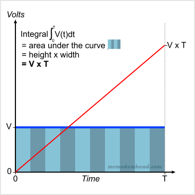
To accomplish this, an integrating converter is used. To avoid getting into too much calculus, for the purposes of this discussion we can define integration as computing the area under a curve. A DC voltage that does not vary with time is about the simplest “curve” there is, so let’s look at integrating a voltage V for an interval of time T.
In Figure 1 we see the voltage V, represented by the blue line, remains constant for the entire time period. The area under the curve is represented by the progression of shaded rectangles. The calculated area (represented by the red line) starts at zero, but as time progresses, more and more area is added to the total until time T is reached. Calling upon basic geometry, we know that the area of a rectangle is length x width, so the total area under this curve is V x T.

Figure 1.
Integrating a constant DC voltage V for time T results in a linear ramp that reaches the value V x T.
The real world hardly conforms to ideal circumstances, so let’s also look at a DC voltage that has a “noise” component. Suppose that the voltage to be measured is the output of a mains voltage adapter, and that some remnant of the mains waveform is riding on top of the DC voltage. If we simply sampled that voltage at two different points in time we could get very different values. But this is a digital multimeter, and we’re interested in characterizing this DC voltage over a period of time, without worrying too much about the instantaneous values. (If we were concerned with that, we’d be using an oscilloscope.)
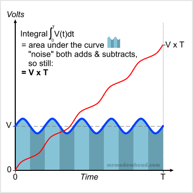
Performing the integration is still the same process of computing the area under the curve, as shown in Figure 2. If we look at the blocks that were rectangles in the last example, this time they’re a little more complicated. But if you look closely, you will see that the “noise” adds a little extra area part of the time, and subtracts a little area during the other part. As long as the noise is symmetrical, it will add as much as it will subtract, and our result will be the same V x T.

Figure 2.
Integrating a DC voltage V with a noise component for time T results in a slightly non-linear ramp that reaches the value V x T.
Saying that the noise signal is symmetrical is another way of saying that if that signal were measured by itself, it would have an average of zero volts. And if the noise is not symmetrical, it will have a non-zero average, and that will either add to, or subtract from any DC voltage it is riding on. That will change the integration result. But that would also mean that the noise has affected our DC voltage, and we do want to measure that. So we still have a correct and meaningful result by integrating.
You’ve probably gotten the idea by now, that by computing this integration value for a period of time, we are going to end up finding the average of our voltage input during that time. And that is correct. After all, that’s the first step of getting the average of a group of values, adding them up. By doing this, we’ve minimized the result of any spurious noise, because it just becomes a small part of the aggregate value. But what to do with this aggregate value?
Up One Side and Down the Other
Let’s introduce two new concepts: integrating a negative value, and not starting at zero. Neither one is complicated. When integrating a positive value, the result increases with time, resulting in a positive slope. When integrating a negative value, the result decreases with time, resulting in a negative or downward slope.
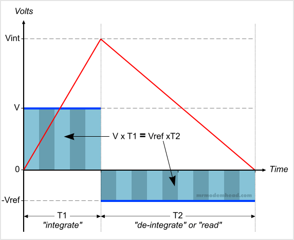
So if we integrate a positive voltage to some positive integration result Vint, and then immediately start integrating a negative voltage without changing anything else, our integrated value will start to drop back down towards zero. Figure 3 shows two such consecutive operations. During time T1 we integrate the input voltage we wish to measure. The result of that operation is Vint. Then starting at Vint, we integrate a negative voltage Vref. After a time T2, the integrated value will return to zero.
The second time period is often called the “de-integration” or “read” period. And it gives us the reason for calling this system a “dual-slope” integrating ADC.

Figure 3.
Two consecutive integration periods yields two slopes.
Since we started the second integration at the value produced by the first (Vint) and waited until it became zero, we can establish that the areas under the two curves are equal. That means that V x T1 = Vref x T2. Solving for V yields V = Vref x (T2/T1). That bears repeating in big letters:
V = Vref ( T2/T1 )
This is important because it means that if we have a nice stable reference voltage available (that we can invert the polarity of), then we’ve reduced the problem of measuring an unknown input voltage down to a matter of measuring time. And time is easy to measure in the digital domain because all we have to do is count clock cycles!
Now let’s make things really easy. Let’s set T1 to a fixed number of clock cycles based on a power of 10, say 1000. Further, let’s use a Vref that is also a power of 1o, say 1V. That means:
V = 1 volt ( T2/1000 )
So let’s take an unknown voltage and integrate it for 1000 clock cycles. Then start counting clock cycles while integrating a fixed negative 1V reference voltage. We wait until the integrated value reaches zero, at which point we stop counting the clock cycles. Now suppose we happen to count 1250 cycles for T2. Then V = 1volt x 1250/1000 or 1.250V. Because of our cleverly arranged constant values, a direct decimal representation of the unknown voltage is sitting right there in the clock counter. All we have to do is simply display the counter value in a nice digital display, and put the decimal point in the right place.
At this point, we have not covered what kind of real-world electronic circuitry can perform these operations. So in the next “DMM Basics” post we’ll take a look at the ICL7106 ADC and LCD driver chip (datasheet). In the meantime, have a look at this excellent video on op-amp basics, in particular the integrator circuit.

Hope you dont mind, but ive stolen this page with a web page to pdf firefox plugin.
Its not often someone describes this subject without making my brain hurt lol.
Also i have knicked a copy of the 8050 led display conversion, as i have one as you know.
Anything i copy from your site is just for my learning 🙂
If you find it useful, by all means snag a copy. But I retain the movie rights.
Im about to show my lack of intellegence now 🙂
I had to skip most of your text as i have to visualise the process and i lose track with
the complex discription side, im a bit thick you see lol.
For standing dc voltage in a multimeter only, nothing else.
I saw the integrator to be like a constant current generator, so when the input voltage is applied it is used for a set number of clock cycles to charge a capacitor with constant
current, so the charge voltage stored is done in a linear way.
The Discharge side does the same thing but with the reference voltage inverted
(ref capacitor charge reversed via switches), and the clock cycles are counted untill
a voltage threshold trigger point is reached, then the clock cycles are displayed.
Im sure im so so wrong in many ways, but my limited intellegence sometimes blinds
me to seeing things the way they actually are.
Your text is saved, its important for me to get my head around it one day :-))
Not wrong at all. I would just add that the integrator is really a voltage-to-current converter, so that the integrating capacitor charge current actually varies with the input voltage, remaining constant only if the input voltage remains constant.
And for the “discharge” (de-integrate) side, the charge voltage threshold is the point where V x T1 = Vref x T2, which will be zero assuming the “charge” (integrate) phase started at zero.
Ahh thankyou, a voltage to current converter.
Makes even better sense now 🙂
Thanks for the reply 🙂
Hi ModemHead,
Recently I started an article about multimeter for my blog (totally non-commercial and ad free) and found that your article is just what I’m looking for on subject of ADC.
I like your style of explaining things and like to translate yours into Korean instead of writing my own, so I wonder if it’s okay with you and give me a permission to do that? I’ll provide your credit on the article and direct link to your site
so that anyone who’s interested in original author could visit your blog.
I’ll be waiting for your reply soon. Thanks.
White Turtle from South Korea
Hello White Turtle,
Thanks for your interest in my article, I’m very glad you find it useful. You have my permission to use it as you described, and good luck with your project.