
 After buying and refurbishing some older Fluke DMMs for use on my workbench during the past couple years, I recently decided to try something a little more complicated. So I found a crusty old “parts or repair” Tektronix 465 on eBay. It looked physically intact and the pix showed that it at least made a dot when the beam-finder button was pushed. Good enough. I set about to win the auction, and did.
The scope arrived safe and sound since it was well-packed. And yep, it was a bit dirty and pretty much dead. Let’s take a look inside.


Powering it on, I got a dot when I pressed the beam-finder, and that was it. Checked all the power supplies, all of them are pretty much spot-on with no ripple to speak of. All of the transistors are socketed, so since there were some signs of oxidation, I re-seated every transistor I could get my fingers on. Horizontal sweep appears! Looks linear and perfectly normal. But no vertical deflection at all, including the position controls. And the intensity control has to be turned all the way up to see anything. Which leads to the trace disappearing at higher sweep speeds.
The Tek 465 has a Trig View switch which basically disconnects both vertical amps and instead connects the vertical deflection driver to a trigger signal sample from the sweep/trigger board. It’s a cam and leaf arrangement built right onto the PC board. Punching this switch vigorously showed some noisy vertical deflection. Examining the switch I can see some crud in it. I cleaned it by soaking a paper strip in IPA and moving it back and forth between the contacts.
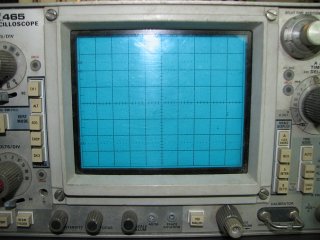
Vertical deflection now looks pretty good, so on to the intensity problem. Selecting either the Mix or A-intensified horizontal modes should result in the delayed section of the sweep being very bright. Instead, it seems this section is about the only thing readily visible. The regular part of the trace is just barely visible with the intensity turned to max. Not normal, but somewhat promising.
The high voltage supply is supposed to be -2450V. Checking it shows -2400V, so I tweaked the HV adjustment up a bit. The manual says the CRT grid bias should be adjusted for a dim dot in X-Y mode when the intensity control is set for a 20V output on the Z-axis (intensity) amp. Interesting, the Z-axis amp output will only go to 15V with the control at max. The Z-axis amp consists of 4 discrete transistors, so I check through it and can’t find anything wrong. The inputs to this amp are several diode-ORed signals from various places. Blanking inputs pull up, intensifying inputs pull down. So I start checking the blanking inputs, and when I get to the Chopped Blanking input, it looks fishy. Pulling the cable for this input results in a very bright trace!
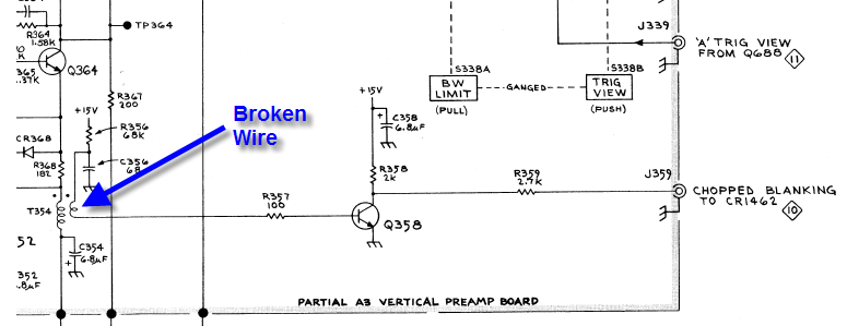
Fig. 1 – Chopped Blanking Drive
Working backwards, the chopped blanking signal comes from a common-emitter transistor amp, which is fed from a small toroidal coupling transformer. It’s supposed to provide beam blanking while the beam traverses from one channel to the other in chop mode. The transistor tests good, but is never turning on because it appears to have no DC bias. This results in the collector resistor pulling up the Z-axis input really hard. Found it! The secondary winding on the toroid is broken right in the middle. It appears to have taken a serious blow, perhaps from the case of the scope.
As a temporary fix, I scraped some enamel off of each broken end and made a little solder splice. I’ll make a more permanent repair after locating some enameled wire to rewind the secondary.
Success!
Further checkout reveals no other major problem that I can find. Both vertical and horizontal calibration is a little off, but not too much. The front panel area needs serious cleaning, and of course all the vertical attenuator and timebase switch contacts as well. I’m pleased and somewhat surprised that the scope is operating this well without having to replace a single component (except for the bypass cap I broke with a pair of needle-nose pliers.)


After removing the sweep/trigger board, the timebase board is accessible. More delicate cam-and-leaf stuff to clean in the timebase control. I used more paper strips and IPA, then finished up with some Caig Deoxit for good measure.
The front panel is very grimy and the structural plate of aluminum behind it is suffering from oxidation/corrosion, especially around the holes. This scope has not seen a humidity-controlled environment in years.
The front panel was cleaned with IPA, then scrubbed with a toothbrush and baking soda toothpaste. All the knobs and plastic bits got the same treatment. A very tedious job, but the results are pretty good.
The BNC jacks were cleaned with a rotary tool and wire brush attachment. At least on the outside, not sure how to get the inside part. The BNC jacks are silver-plated, but the wire brush is not abrasive if used with gentle pressure. The X10 read-out rings were flaky before cleaning, but work nicely afterwards. The front aluminum structural plate was cleaned with a rotary tool and emery wheel. No more corrosion.
The old power cord was stiff, cracked and nasty-looking, so a new one was installed. The old strain relief was cleaned and re-installed along with the new cord.


After re-assembly and re-testing, the trigger-view switch acted up again. I cleaned it once more with IPA and also treated it with a small amount Caig Deoxit. It has behaved properly since then.
I don’t really have the gear for a proper calibration, but it’s pretty easy to get the vertical gain adjusted with just an accurate DC reference (a good DMM will suffice.) DC balance adjustments are also straightforward. I decided that the horizontal calibration was close enough to not worry about it. During these procedures, I found that some vertical attenuator settings gave a noisy, fat trace. Pulled the vertical board again and found more dirty contacts on the back side. There was some green contamination on the gold plating.
While the vertical board was back out, the faulty coupling transformer was rewound for a more permanent repair. Fortunately, you can still get some useful stuff at Radio Shack, like magnet wire.
Channel 2 was intermittent after reassembly. I noted that tapping on the vertical amp board had an effect, so using the old poke-it-with-a-wooden-stick method, I tracked down and found a broken carbon-composition resistor upsetting the DC balance. Probably a self-inflicted wound from getting the board out and back in. Yet more intermittent performance problems was caused by two dogbone caps touching each other. Not a huge fan of this flying-lead construction method, but I guess that was the way it was done at the time.
Scrubbed down and cleaned the dirty shell. Banged out the dents. It’s scratched up a bit, but serviceable. Was looking for Tektronix Blue paint, but I think I’ll leave it as is. More character this way. 🙂


 were touching, causing some intermittent problems. The fat parts on the end are wire, insulated only by paint.")

This repair and restoration was performed in January 2012. I am writing this in November, and the scope is still going strong. Despite the fact that I have newer, better scopes, this 465 has become my favorite for day-to-day use.
Discussion of this topic can be found at EEVBlog Forum.
Enjoyed your write-up on this scope. I am just starting to do the same with a Tek 464 I got off Ebay. Your article will definitely help with my own restoration. Loved working with these scopes back in my Navy days.
Thanks and good luck with your 464. Consider sharing a few pictures of your work at your favorite forum! I take lots of inspiration from new and old equipment fans at EEVBlog.
loved you blog and you did a bang up job of repair and referb. kudos on a job well done. I too love these old scopes and am starting a simlar referb on a dead 465m. I can only hope that I have as great an out come as the scope that you brought back to life. I too have a few “better” scopes at least newer would be the way I think of them. personally the “new” digital scopes are a waste of time, much of the time I just want to see the signal, and don’t need to have the scope analize the circuit for me. I think to myself isn’t that why I spent 12 years at UCLA and beside I like to do things for myself!
It’s great to find that defective part, on my own, guess I must be strange but then they say that about anybody that “plays” with resistors. 🙂 that’s what they said in high school, that made you a nerd. well guess I am because I REALLY LIKED YOUR ARTICLE!!!
Thanks for your kind comments and support. New digital scopes aren’t all that bad, they’re really quite good at capturing slow or aperiodic events.
Very nice post! I will be doing this to two tektronix scopes that I got for really low prices (think > $5) a 465 and a 435. Hoping for good results!
I have all the electronic componets from a tek 453 scope jonyoungblood??me????
Found your blog while looking for someone to fix my old (circa 1972) 465. I’m the original owner of this scope and it saw daily (often 18 hr+/day) use until 1983, then very intermittent use until 1990, and nothing since. It’s been following me thru 8 moves. When last I powered it up , the sweep control was flaky. After reading your blog, I thought, WTF???!!!, I spent 7 years (on and off) getting an EE degree, and then decades of hardware design and debugging experience and I’m looking for someone to fix my scope!!!! Shame on me!!!!. Will locate the cleaning stuff you used and clear off my bench and get to work this winter. Thanks for the blog and the good insperation.
BTW…. have used any number of digital scopes over the last 20+ years, and while the storage ability of the new digitals is nice, none of the ones I’ve used has the clean sharp trace of the 465. As someone else posted above, the new digitals are”good for slow, aperiodic events”. Looking forward to getting my old warhorse running again.
I know this one was a while back, but a repair is a repair 🙂
That came up a treat, the sharp waveform just shows how well the vertical amplifiers and focus is doing, that was well worth the purchase and work, nice scope 🙂
Ive found the timebases love to stop dead, followed by the input amplifiers and ill powersupplys, but we love a little pain dont we ha ha 🙂
Ill take this chance to bore you stiff and list my old crud.
TeleQuipment D32 oscilliscope portable (Bad joint city, but i like it for some reason)
Cossor CDU150 Scope, very old, works when it wants to lol.
Maplin Gold Mf100 counter (works without a fault)
Racal Dana 1998 counter (10mhz standard was dead, loverly counter)
A youtuber called gerry sweeny posted ocxo update for this dana, i may go for it one day as the 10mhz reference has “Drift-icus”.
I’ve put quite a few hours on this unit since the repair and it’s still working great. It was a great $68 investment. I use it all the time for trouble-shooting. I prefer the nice “clunking” tactile feedback of the controls. No menus or rotary encoders that spin all the way around and around!
I thought Drifticus was a homeless gladiator.
Your madder than me (if thats possible).
Im maximus drifticus, commander of … of my cardboard box, can you spare a dollar for a wounded gladiator mis-ta.
yep i can see what you mean 🙂
Old article but still very relevant. Thanks you!!
Bill
Hi to all members!
I have a problem with Tektronix 465
I made a little repair but the problem exist
Before repair only -8V was bad , -0.12V after is -6.2V
On TP are +111.4V , +54.9V , +15V , +4.6V and -6.2V and now all three(newone) CR1561 , CR1551 , and CR1541 are hot
The bulb in Highvoltage section blinking!
The resistans -8v to Ground is 55 ohm
Any help will be good!
Thank you!