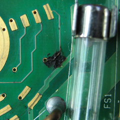
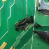
 No this is not about green energy or climate change. It’s about DMM repair, of course. I found it interesting for two reasons, the fact that a very simple fault almost escaped detection, and that the root cause was, while totally obvious to the naked eye, possible to dismiss as just a cosmetic problem.
The victim in this case is a fairly recent Ideal-branded multimeter, a model 61-481 (from Taiwanese maker APPA Technology Corp.) It was the subject of a teardown post over at the EEVblog forum, and then passed by my workbench on the way to someone else. The DMM was described as basically working, but acting a bit funny and not reading voltage correctly in some ranges.
My usual method of testing is to connect the meter to a variable DC power supply, in parallel with another trusted DMM, and see if the readings agree as the voltage is varied from zero on up to the supply maximum. This one agreed within a few counts of the reference DMM all the way from zero to 60VDC. Even the small 5.000V reference board that I use produced a reading of 4.99V, which is fine. [Note for future reference that the TI REF5050 chip used on that device is capable of sourcing 10mA.]
Living Life By the Drop
A clarification on the reported symptoms revealed that when the unit was deemed faulty, it was tested with AA and 9V batteries, and read low on the 9V battery, while reading the AA correctly as compared to a known-good DMM. The difference between those two batteries? Effective internal resistance. A 9V battery has a higher internal resistance than an AA battery, even more so if it has some age on it and is a little weak. A sufficient amount of current draw could lead to a significant voltage drop.
A normal, modern DMM has a high input impedance, usually 10 Megohms, which means it should not draw enough current from a voltage source, even a weak battery, that would cause any appreciable voltage drop. (This is why multimeters do not make the best battery testers.)
But what if the DMM was faulty and its input impedance had dropped to a point where it was drawing enough current to affect a high-internal-resistance source like a weak 9V battery?An ideal 10V source with a 10 Megohm load should produce a current of 1 μA. (10V/10,000,000Ω = 0.000001A) For a controlled diagnostic test, let’s connect the the suspect unit to a 10V source through another DMM, configured to measure micro-amps. The ammeter’s 100Ω shunt will serve to represent the internal resistance of a battery, as well as allowing us to measure the current. This test shows the Ideal to be drawing 3708μA! That’s 3.7mA, definitely enough to bring down a weak battery. And indeed we can see that 0.37V is being dropped across the 100Ω shunt, yielding a 9.63V reading on the faulty DMM. Ironically, this reading is completely accurate, but due to an exaggerated observer effect, is also completely wrong.
Spitzensparken!
Opening the meter up, there are no problems immediately visible. But after removing the switch rotor, it’s clear there has been a spectacular “event” of some sort. It appears that the meter was subjected to an over-voltage input, causing an arc to flash over from one PCB track to another. It would be easy to dismiss this as “just a black mark” on the PCB, but remember that a printed-circuit board is comprised of an organic resin and glass fibers. When organics get hot enough to combust, the hydrogen reacts with oxygen, leaving the carbon behind. And in addition to causing atmospheric problems, carbon conducts!
Probing with an ohmmeter between the middle of the blackened area and one of the adjacent copper tracks yields an unsteady reading of 150 to 2000 ohms, depending on how the probe is held. This is forming a shunt path between unit’s input jacks, causing the lowered input impedance and higher current draw. Simple repair: remove the carbon residue.
The repair was accomplished by scraping away the carbonized material and then routing with a rotary tool to make sure it was all gone. It might have been useful to cut all the way through the board, but there are copper tracks on the other side. Repeating the current-draw test shows that the low impedance leakage path has been removed, and the meter is back to normal. Fortunately, nothing else in the meter was damaged.
The moral(s) of the story? DC power supplies do not make a complete DMM test. Always look under the switch rotors. And remember that organic materials that start out as insulators, can become very good conductors after being subjected to enough heat to cause combustion. Proving once again, there’s magic smoke in everything.


Thats an odd one indeed.
Ive had old washing machines that had a similar problem, the oh so old mechanical
program switch is soldered to a pcb that carries the full mains voltage of 240v or Ouch 🙂
The pcb became conductive and smoke signals of panic appear from machine, i did much the same as you did, first i made a cup of tea and looked out of the window while drinking it lol, then i took a craft drill with abrasive bit and cut through the carbonised pcb to create a portal to another world… i mean a hole lol.
Anti corona laquer was applyed to the raw pcb to seal it up, its all i had at the time lol.
Back to the meter, i hate that switch, fancy running the sprung contacts over the tracks supplying them, ive seen £5 jobs done better than that!.
Got slightly confised 🙂 with the maths top of page, yes it could read its share of the potential correctly, but the 3.7ma is not the ideal current, the true Ideal should have been less than 1ua if the voltmeter was fine.
You omitted the faulty meter resistance of about 2.6k, Just to confuse my daft brain ha ha 🙂
I being a lazy sod would have bunged a 10m Ohm resistor in series with the 10v and expected the meter to show just under 1/2 supply 🙂
Smashing write up, i do enjoy your repairs and mental torture 🙂 🙂
Sorry did not mean to cause any confusion. Speaking of which, 10m ohm is 0.010 ohms. (Useless pedants will be pedantic.) A 10M ohm series resistor would illustrate the fault, but would not provide an excuse to include all the nice Fluke 87s in the photo. 🙂
I don’t think the rotary switch design with the contacts running over the tracks is uncommon. But I don’t recall seeing it in a “premium” meter. If you haven’t seen it, see this Elenco LCR meter for a worse way to do it. They run the contacts right over the vias, and the tracks are not even masked.
Ooow, i did write that wrongly, ill have to nip to the bottom of the garden and shout over the fence “Horlicks!!”, for no reason other than not swearing 🙂
Yes you are correct as allways master, i like to see multimeters in good use 🙂
I used my so cheap yellow mastech 830b yesterday to find a short circuit on a frends old technics amplifier, it kept blowing the 2 x 6.3 amp fuses in the main psu, the fault was a dead diode in a sub bridge rectifier that fed the p.a with +/- 56v, thank god it wasnt the duel channel multi legged beasty bolted to a massive heatsink that shorted.
It looked like a special p.a package, buying one would be hard and not worth the repair.
A 1N5406 was my fix, its what i had in my diode tin, the original diode was an odd P300DLF one.
Keep up the good work 🙂
I learn interesting new words when you make comments. But if I go outside and yell Horlicks in my slow southern US drawl, I may get arrested.
Good repair. Keep calm and carry on.
A Fluke 117 which had the plastic screen protector still on, I found death lurked in minuscule corrosion products? at the switch contacts, and one place under the display. Unfortunately, even very dedicated cleaning and drying out did not bring life back: continue to get (batt) and (F11-) at switch on. Up to 10V from a bench supply did not help. Fluke provide no info other than “needs service if F116 shows”. Have checked for Vcc’s and shorted caps, all good. What more can I do?