 The Fluke 26-III and 79-III models are identical except for the model number. This model adds some extra features not available on the 77-III (and its identical twin the 23-III), like frequency and capacitance measurement, 4000 counts vs. 3200, RMS response, and a faster update speed. It also has a special 40-ohm resistance range that provides 10 milli-ohm resolution, aimed at electricians who may want to measure and compare contact resistances on relays and switches. It’s not a bad tool for the electronics workbench either, provided you do not need precise measurements of current in the micro-amp range. It does however have 1μA resolution in its lowest current range (4mA).
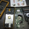
This unit arrives in a completely non-functional state. It doesn’t look too bad on the outside, but attempting to power up with a fresh battery results in absolutely nothing on the display. Disassembly and a quick visual inspection, with particular attention to the battery connections, reveals no apparent damage to either the components or either side of the printed circuit board (PCB). Both fuses are blown, but that’s about par for the course with a used multimeter.
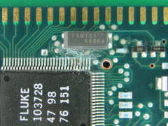
One thing of particular note about the construction of this model, is that the microprocessor at the top is completely covered with a grounded metal shield. It obscures the pins of the quad flat-pack (QFP) chip.
Diagnosis begins by checking the current draw of the meter when powering from a DC power supply set to 8.5V. It measures 120μA, which is way lower than expected if this meter were actually running. When turned on, there appears to be a regulated 2.98V from the COM jack to the positive battery terminal. This means there’s at least one voltage regulator working in the power supply section (wherever that is, I’m working with no schematic here.) But there must be no load on the supply, as if something is disconnected.
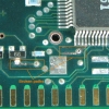
Closer inspection reveals a possible problem up near the microprocessor and under the shield. The shield has to be removed for a better look. It appears we have a small area of major crud. This is isolated and a long way from the battery, so it would be hard to blame it on battery leakage. In any case it appears something corrosive has come into contact with the PCB in this area.
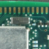
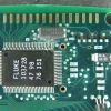
Time for scrubbing with a stiff brush and isopropyl alcohol (IPA). After the crud is removed, it becomes obvious that a copper pad near the microprocessor has eroded, leaving a trace broken and disconnected. The pins of the microprocessor appear to be OK, despite a little discoloration. There is a large 4-pin SMD component (clock crystal) in the area that will make repairs difficult, so it gets removed. More cleaning and examination shows that there is also another area of erosion on that same trace.
Repairs to the broken trace are made with 30ga wire-wrap wire, stripped of its kynar insulation and tinned. The 4-pin SMD crystal is re-soldered. Checking the supply current now shows a more healthy 1.05mA is being drawn. This is very promising.
The shield is re-soldered on, and the LCD re-installed. The meter boots up and displays all zeros on VDC! It measures resistance correctly, but checking with a 5.000V reference shows the calibration is off. There is a pretty good chance that I may have disturbed the calibration pot with my brush while I was doing the initial cleaning. Recommended calibration voltage is 3.5V, so a quick adjustment at that level restores calibration. After cleaning the plastic parts and giving the scratchy lens a polish, this meter is ready for service again.
DMMCheck calibration check results for this Fluke 26-III:
| Reference | Reading | Notes | |
| DC | 5V | 5.00 | |
| 1mA | 1.000 | ||
| AC | 5V | 5.03 | |
| 1mA | 1.003 | ||
| Ohms | 100Ω | 100.1 | 0.2 with leads shorted |
| 1K | 1.000 | ||
| 10K | 10.00 | ||
| 100K | 99.8 | ||

Ooow now thats a good one 🙂
Where did the dampness come from, ive seen the same kind of damage to mobile phones where the owner had sweatted and the phone pcb suffered.
Water and salt, hmm.
That component looked like a resonator or crystal, the main clock for the processing and multiplexing i would assume.
So the resistance side must use something like ratio metric methods, and as its a ratio thing the reference is redundant.
And for voltage/current the reference is needed to measure the voltage magnitude generated via resistor shunts or series drop.
Smashing write up and crisp piccys 🙂 , you have a superb meter, i would be green with envy if i was that kind of person lol.
Im sure you will put me straight if im talking jibberish ha ha 🙂
I don’t know what the four-legged component is, I never found a datasheet for that part number.
I thought maybe a diode bridge although I don’t know why one would be in that spot. Never seen a resonator/oscillator in that kind of plastic package, but given the proximity to the processor, that might make more sense.[Edit: Forget all that blathering, it’s a 131.072kHz plastic-encased crystal.]You are absolutely correct about the resistance measuring technique being ratio-metric. Has nothing to do with the internal voltage reference, hence no dependence on the DCV calibration (which is usually a tweak to that reference.) In fact, the dual-slope A/D converter in these DMMs always converts the ratio of two voltages to time. A clock signal is counted during that time interval and the result is displayed. When measuring voltage, this will be the ratio of the unknown voltage to the reference voltage. If the reference is one times some power of ten, then all you have to do is put the decimal in the right place.
For resistance, the unknown resistance and a precision resistor (usually one of the voltage divider legs doing dual duty) is placed in series. A voltage source (not a constant-current source) supplies the test current. The somewhat arbitrary voltage across the precision resistor is taken as the reference voltage. The ratio of the voltage across the unknown resistance and this reference voltage gives the ratio of the unknown resistance to the precision resistor, since the current thru both is the same (series connection.)
This is why checking the resistance range of a DMM will not really tell you if the meter is calibrated, but it will tell you how accurate the voltage divider resistors are! And whether the front end is healthy (no current leakage.) For my usual 805.8-ohm test resistor, I find that every single Fluke in my wheelbarrow will read 805 or 806. Cheaper meters always have a wider range, usually 802 to 810.
I do like you allowing me to see your thoughts forming 🙂
I tend to leave my mental ramblings on the scrap of paper, then throw it away before
anyone has a chance to laugh lol 🙂
131 khz, i thought it was a ceramic resinator but who cares as it works 🙂
Ive repaired bucket loads of remote controls with impact damage, mostly the resinator
had broken off its strips, a glue down with bostic or silicone sealer then resolder it and
all is well again 🙂
Thanks for confirming my crude understanding, its great to know someone that knows
what he is doing, this hobby site of yours is a great idea, hopefully more people find it 🙂
Im not allways very sharp, and your repairs kick the braincells nicely :-))
Because of you, ive been able to see the insides and understand flukes better 🙂
Ill have to sneak up and raid your wheelbarrow of excellence lol.
My unsung research assistant came up with Fox Electronics as the source of the (now-discontinued) FSM series, and the fact that 131.072 = 32.768 x 4. I don’t have a service manual for this model, but other models’ manuals have Y1 listed as a crystal, either 32.768kHz or 131.072kHz. So for lack of a better understanding, I just called it a crystal.
Slamming a remote down on a table in a fit of disgust at something seen on the tube will surely damage a ceramic resonator. But Mr. ModemHead wouldn’t know a thing about that. No-sir-eee.
I don’t always know what I’m doing, that’s the reason I don’t do video. It’s easier to leave out the really stupid parts. 🙂
Excellent job of soldering those little wires to the traces. I find soldering little wires like this on a PCB is one of the hardest and frustrating type of repairs I have had to do in my limited experience.
Thanks for taking the time to share your repair efforts, I find them very interesting. The only problem I have with your blog is that it tempts me to acquire dead meters so that I can attempt my own repairs. While this in itself is not a problem, I do not have time to work on all my current projects so I do not need to add more to the pile.
Thanks for the kind remarks. The secret to little wires: let the coffee pot go dry, lots of flux, and good reading glasses.
heey guys,
i know the fluke 26 III is no more sold.
But i want to know what price you payed for it.
Because my uncle gave me one but i want to sell it.
Greetz
Recent eBay sales of Fluke 26-III and 79-III models range from $75 to $120 USD, averaging somewhere around $105 USD.
Very interesting write up and the pics are a big help. I have a Fluke 26lll and it has the same symptom. It did get wet due to my carelessness, I left it on a bench under roof but no walls on three sides. A blowing rain caused the moisture. I opened it up and dried it well and at first it would light up but not really come to life. After reading this and seeing the pics I may give it a shot at repair. It has been out of commission for a couple of years so corrosion is a very viable possibility. If I have any luck with it I’ll come back here with an update. Thanks for this write up!
Good luck! Use magnification, those little eroded spots like to hide.
I have 3 fluke 179 with same sinthom ( fault ) on ohm field display 1/2 of real value
volt and amp ok , overload net ok . on ohm field with probe in air display ist 424, 4 k ( 400- 450 K)soryy for my english please hlp
I don’t really understand your problem, so the best suggestion I have is to check the front end components. The flame-proof resistor should measure 1K and the PTC thermistor should measure somewhere around 1K. The MOVs should measure open-circuit.
Thanks for your post! I have a Fluke 79 iii. I hooked something up the wrong way (was sleepy) and two internal components got fried. From your picture of the main board, the two components I’m talking about are in the right bottom corner above the COM and V jack inputs. One looks pretty clearly like a resistor, but the other one–a little ceramic disk–I have no idea. Any help identifying these would be amazing. Thanks.
-Erik
I don’t have a service manual for these models, so exact part numbers are hard to come by. But maybe I can describe those components in a general way.
The disk is a positive temperature coefficent (PTC) thermistor. It protects the meter when voltage is accidentally applied in ohms mode. In most Flukes this is a 1.5K (@25C) 30% tolerance part.
The resistor is usually either a 3.5K 5W wirewound (dark gray) or a 1K 2W fusible/flame-proof (light green or brown). It is responsible for dissipating power if/when the MOVs conduct during an overload. The unit pictured in my post here looks like the wirewound. I don’t have that exact meter anymore, but a 26-III that I do still have has the light green fusible resistor in it. Fluke did seem to like to tweak the input components between board revisions.
When looking for a substitute for either of these components, ideally the part should be rated for 1000V. That could be a tall order, so you can pretty much figure on de-rating the meter when using non-Fluke parts.
You can temporarily substitute a plain 1K resistor for both of these components to check and see if the rest of the meter still works. If it doesn’t, obviously something else has been fried and you may have bigger problems.
Hi, nice repair job. You seem to know your way around these DMM so I have, if You don’t mind, a small question for you. I got a Fluke 175 from a friend and all it does is display the 4 center dashes, – – – -. does this sound familiar to you? I opened it up, fuses where missing and found some small corrosion but nothing too bad. I replaced the batt, shorted the fuses. If I start it up while pressing the hold-button the entire LCD lights up, so that seems to work fine, but apart from that nothing. Do you have any suggestions?
Thanks in advance,
D
Unfortunately there is no publicly-available schematics or service information available on this series of models, so we have to speculate. The “- – – -” error message seems to show up when the microcontroller loses communication with other parts of the circuit, like the A/D chip or the function selection mechanism (see this comment). As you can imagine, there are a multitude of reasons this can happen. Be sure to optically inspect every trace and via, and use magnification. Sometimes vias lose connection from one side of the board to the other because of corrosion. Gunk inside the via holes is a tell-tale sign.
I have a Fluke 26 III and it has some corrosion. I cleaned it with distilled water and a soft toothbrush and used compressed air to help dry it. The AD 373 chip has the #7 leg broken from the chip. It looked like corosion ate through it. I am afraid to try and remove the cover from the processor to clean and check it. I have a small pencil soldering iron but the tip looks like a telephone pole compared to the traces. Could I send it to you for repairs? I know it is going to need the AD 737 chip. The only thing I have done is clean off the majority of corosion that I could see.