
A common problem with Fluke 8010A, 8012A, and 8050A bench/portable DMMs is the LCD will ‘bleed’ or turn completely dark. Replacements are hard to come by. But if some common 7-segment LCD displays are hacked in, you get a meter that can be read in the dark.
I did this project before starting this blog and did not fully photo-document the process. But you get the idea.


This is not an original idea. More 8050A LED conversions from around the web:
- Fluke 8050A LCD display replaced with LED seven-segment
- Fluke8050A Hi Res Display
- A new LED display for a Fluke 8050A multimeter
Have you ever done a conversion for an 8010a? Do you have any suggestions or ideas?
Thanks
Never had to fix an 8010A display. It only needs a very generic 3-1/2 digit LCD like the one I used for an 8020A replacement, so if the mechanical mounting issues can be worked out, that might be a possibility.
My Fluke 8050A meter head (LCD) is not showing any digits and I believe the meter is perfectly functional. If I can convert the display to LED, it will be great. Is any circuitry involved and if so can you send me that circuitry so that I can do some conversion of my meter to LED display.
Thanks and regards
William
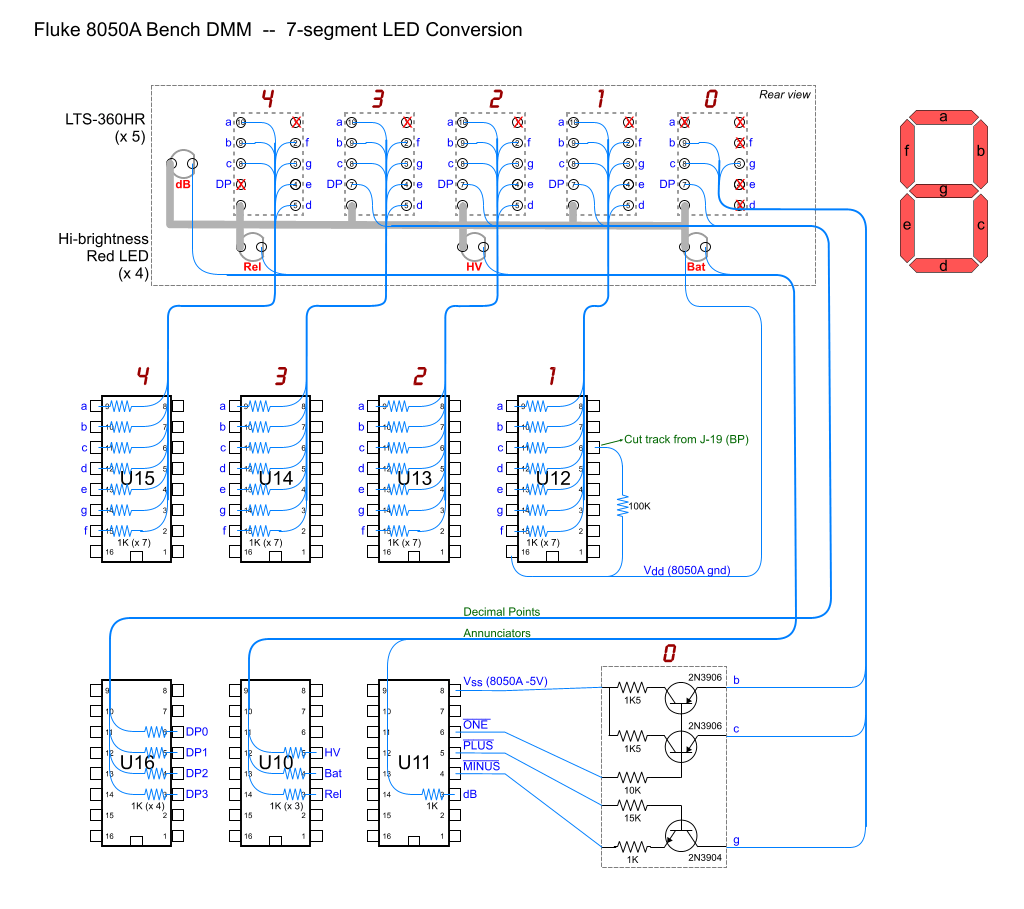
In addition to the series resistors for each LED segment, there is a small circuit to deal with the minus sign and to drive the ‘one’ leading digit without overloading the driver IC. All of that is shown in the diagram included in the gallery.
modemhead,
Just wondering: Did you make or buy the power supply in the photos? If the later, which make/model is it? Great work with the display. I have an 8050A and the display is in very good shape. I use it all the time and, though it’s a manual ranging DMM, I still enjoy it. Great performance for such an old design. Thanks for publishing this.
Sorry for the late reply, I just noticed your question about the power supply. The power supply is home-made. Thanks for your kind words.
I just purchased an 8050a with a dying LCD. Thinking about using your guide to swap for an LED. Is the schematic in the first picture all that needs to be done? Besides the pull up resistor and trace cut on the reverse of the board.
Yes all the modifications are shown in the schematic, and are limited to the display board only. No changes on the 8050A main board.
Thank you sir! Really looking forward to the final product.
I’ll be using green displays for my conversion.
Hi,
Thanks for this mod, it really works very well.
I would like to know if I can use this post and or content to publish it in our HAM Radio Club News Letter called “QRX” we normally have about 4 publications and we share what we have done in the past quarter.
Thank you..
I’m pleased to know it was useful. By all means, pass it on.
Thanks will do.
Hello.
Great work Mr Modemhead! In the diagram, what resistor wattage are you using and is it necessary to insulate all the resistors? How is the LED display board fastened to the front panel? Is it hot glue? Thanks.
Ron
Thanks, it was kind of a bodge job, but even after 3+ years, it’s still working great. The resistors are 1/8 watt. I insulated the connections just to keep them from accidentally shorting to adjacent wire. Probably overkill.
The LED board is indeed fastened with a small bead of hot glue. You can barely see it in image #10. And if I recall correctly, that excess board sticking out on the left had to be trimmed off because it bumped into something.
Hello!
I purchased the prototype boards, resistors and LED’s. The only thing left for me to buy is some hookup wire. What gauge and wattage do you recommend? Thanks.
Ron
I used wire-wrap wire, which is 30 gauge kynar-insulated. Came from Radio Shack!
With the design shown on another web page http://lous.home.xs4all.nl/fluke/Fluke8050Asite.html, the circuit for “+” and “-” used a BS170 MOSFET. You chose to use 3 transistors (2N3906, 2N3904). Is there an advantage to either design or are they pretty much the same?
It’s difficult to see in the picture, in your final installation, is there plastic film or similar material used as a clear protective cover?
I just used the BJT’s because I had a drawer full of them. I added drivers for the b&c (1) segments so that one CD4054 pin wouldn’t have to provide current for two segments. Those CD405x drivers are pretty weak, they’re meant for LCDs.
The “cover” is a piece of translucent plastic salvaged from the front of an old VCR. Remember those?
I ended up using clear plastic combined with tinted plastic film for the cover. It looks pretty good.
Completed the electrical mod per the diagram. Used Kingbright SA36-11EWA LED’s. Also replaced the original NiCads with two pairs of sub-C NiMH’s. After the mod, the meter displayed a couple of zeros and a decimal point dimly for about a second. Then the entire display became unstable and would display random sets of segments; new announciator LED’s also participate in the random display. Turning the meter back on doesn’t duplicate that initial “good” display. “Scrambled” display is nominally bright. In the process, F3 blew. Triple checked to ensure there are no shorts and all connections are correct. Before the mod, meter was working ok with leaky LCDs. Not sure if the fault is in the display mod or on the main board.
Sounds like you may have power supply problems. Double check that your battery cells are healthy (1.2V or more) and the connections aren’t accidentally reversed.
Agree. Symptoms suggest something is not getting the correct power supply. The meter worked for a couple of minutes last night but some segments did not light up. Then the display became unstable again.
I measured the expected -5V on pins 7 & 8 on U10 – U16, so I think the source of the problem is on the main board. Each pair of the new batteries are putting out 2.8V. I also selected the 3 zener diodes as convenient places to check and voltages were on spec. I’m still looking for more places to check. Perhaps the fault is due to one of the electrolytic capacitors…
You certainly do nice soldering work. Nice job! I plan to do this to my 8050A as well. Thanks for the great rundown and pictures.
Can you comment on the need for the 100k resistor from U12 Pin 6 to ground?
J1P19 is the LCD backplane clock (BP) which is a square wave at about 50Hz. This signal is distributed to all the CD405x driver ICs. It is also the common line for all LCD segments. The driver ICs would normally drive all LCD segments that are supposed to be “on” with an inverted (180° out of phase) copy of the BP signal. Segments that are supposed to be “off” just get a non-inverted copy of the BP signal. This keeps the average voltage across each LCD segment at zero, whether on or off, because LCDs are damaged by a constant bias in one direction (DC).
To convert to common-anode LED operation, we need each active segment to be driven low and stay there as long as the segment is supposed to be on. So cutting the BP signal from J1P19 and pulling up the CD405x inputs to a logic high will accomplish this.
U12P6 is just a convenient place for this 100K pull-up. And since the CMOS drivers are powered by the meter’s -5V rail and ground, logic high (Vdd) is actually ground.
Okay, thanks for the reply. I have seen some of the other similar solutions online but I don’t recall seeing this in those designs.
I plan on trying this sort of, I want to change/add as minimum as possiable however I am confused I thought common cathode would be easier to use, hard to find +-1 but reverse wiring a Avaga 5082-7656 should work and the 5082-7653 is common cathode with resistors and connections at the LCD connector, similar transistor ckt’s to drive the 1 and + upper and lower not sure on the – as I do want that to work correctly. Still learning.
Jeff
Thanks for the inspiration to fix some of my Fluke 8050a’s. Tried to do the process like you show in your pictures but gave up since it was to tedious for me to get it right. I found a great way to construct the LED segments onto the PCB without solder. I used standard Dupont double sided pin strips and cut them into lengths of 5 pins.
After inserting LED’s into board I folded the LED pins inward towards the center of IC. Used care not to have them touch together or the PCB hole trace in the middle.
Using some pressure I was able to insert the Dupont pins into the PCB and grab the LED pins at the same time. Fit was tight but provided a secure and reliable connection.
Completely eliminates the soldering. Dupont connectors will run to back of Fluke where batteries would sit and plug into 1k resistor arrays mounted on PCB with corresponding Dupont pin connectors at this location.
It all plugs together. Working on finishing up connections to the Fluke LED driver pins on the back side of the board (top when installed).
If anyone needs pictures or more information I can provide shortly for all interested.
Great project and documentation by you. Two Thumbs UP!!
Thanks. Gary
This sounds like a great way to do the mod. A link to some pictures would be fantastic! (or email them to the address in the right sidebar and I’ll publish them here.)
I will get some pictures together ASAP. I also eliminated the LED’s on the led display for HV, Rel.and dB by drilling small holes on the face plate ( at the appropriate places below or between the probe inputs) and inserting 3 mm led in each one. Red led for HV, Green for dB, and Yellow for Rel. It is a simple and visual way of seeing what is active without having to read the display itself. If you plan the drill holes carefully you will clear all of the components and interior metal shielding. Will include picture of whole concept ASAP.
Main led display pcb was cut to fit snugly inside the rear portion of the Fluke holder ( as opposed to on the back). I plan to fill void around the led’s and the holder with black silicon leveled flush to give a finished look and to make a secure mounting.
Dear Gary – Your idea of wiring the LEDs with Dupont double sided pin strips is very good. I want to do it that way too. Please send me your photos and suggestions – Udo
I was looking around for a 5 digit display, and found many that only have 14 pins….
How would this work as a 5 digit display? What am I not understanding about the process to make this work?
http://www.ebay.com/itm/0-36-5-Digit-7-Segment-LED-Display-DIP-Common-Anode-Red-/302013832879?hash=item46516d5eaf:g:uIEAAOSwanRXh0EO
–jim
I guess I should add this diagram / schematic.
http://gd1.alicdn.com/imgextra/i1/555072750/T2ZklvXyxXXXXXXXXX_!!555072750.jpg
–jim
That display is multiplexed. It means only one digit can be on at a given time. Cycling through the digits fast enough makes it appear that all are on at the same time. This type of display cannot be retro-fitted into an 8050A without adding more circuitry.
Thank you sir.
Maybe one day I’ll get one and have the time to learn to use it…. Like SO many other things..
–jim
What size LED’s should I buy, .56″ or .36″?
tengo un fluke d810a ya he trabajado con diplay de 7 segmentos en otra clase de
equipos pero con mi fluke no se por donde comenzar cual es el diagrama para este modelo
Any idea where to get a fuse holder for a 8050A?
Hi,
Thanks for the tutorial, it makes almost everything clear.
I have just disassembled my old 8050A with blurred LCD for a LED conversion.
Got cold feet reading a datasheet for the 4054 & 4056 drivers though?
Are the 1k resistors enough to limit the sink current for the segments without damaging the drivers?
Best regards
Andy.
That’s a valid concern, which is why I looked for a high-brightness 7-seg display, and run it at lower than its rated current. The display does not have to be blindingly bright. I did this mod in Oct-2011. With the exception of when I’m out-of-town, I have left my modded meter powered on 24/7 for all those years. It’s still working to this day.
Thank you for the information, I´m now back in my comfort zone.
Best regards
Hi, I have an 8050A without battery option. I had to do this mod because the lcd went bad. It seems all is ok except HV led never goes on, but I have never seen HD annunciator active before, so it was probably faulty before I made the mod.
A major issue regards the “Rel” led. It is ok if for example, in voltage mode you select relative button. But if you switch for another mode for example by pressing dB (with rel mode active), Rel goes off and you have to press another time Rel to switch it on.
I wish I could have this display as my displayed went dead; I have the 8050a with battery option. I am skillfull in installations but I have no programing experience. Would like a KIT with all the parts needed. Any leads to who or website thats sells this. BTW I am in Canada.
It would be wonder full to have more than 4 digits. I can do the calibrations.
I love this circuit because it needs no special programming skill which I do not have. Just need the led chips and 3 transistors. This is fantastic. I built may years very complicated boards with ic chips on vero boards. Thank You so much. Wish there was a parts list.