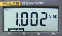
 The first two generations of the popular 70-series Fluke handheld DMMs included the 21 and 23 models, which were the same as the 75 and 77 respectively, except their cases were safety yellow instead of the usual dark gray. The third generation of the 70-series also included the 21-III and 23-III models as well, but they look exactly the same as their 7x-III counterparts. It is my understanding that the only difference was that the 2x-III models were packaged with premium test leads. Just marketing, I suppose.
In any case, this 23-III looks exactly like a 77-III, right down to the markings on the circuit board inside. It is a little dirty but I’ve seen much worse. It was advertised as working for DC, but not AC. During initial check-out, I confirmed this and also noted that the continuity beeper also did not work. DC voltage and resistance measurements were OK.
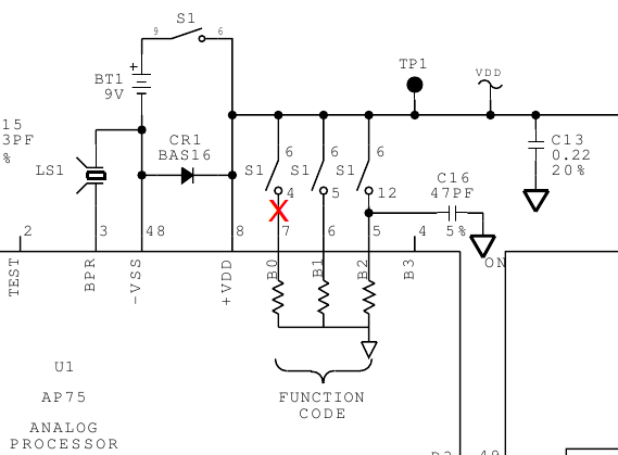
Curiously, the LCD displays VDC when the switch is in the ACV position. It never displays any readings for an AC input, just all zeroes. This detail may be important, because part of the rotary switch is responsible for setting a function code, so that the microprocessor knows what position the switch is in. On this model it is the rear wafer of the rotary switch that sets the function code via 3 logic-level lines, providing up to 8 unique binary combinations. If something is wrong with this circuitry, the analog processor might be “looking” at the wrong inputs for some switch positions.
Toxic Soup
It’s fairly obvious after opening the case that some sort of hazardous waste event occurred inside. It looks like a battery has leaked at some point in the past and the alkaline juice pooled in the bottom, concentrating its corrosive efforts on the piezo buzzer, the battery leads, and parts of the circuit board under the rotary switch.
First order of business is to scrub the board with isopropyl alcohol (IPA), removing the crusty residues. It actually takes two scrubbings to get it all. I use both a stiff-bristled toothbrush and a disposable brush (often called an “acid brush”.) The bristles on the disposable brush are cut down to make them stiffer for scrubbing contaminated areas between components.
The underside of the PCB where the rotary switch terminals are soldered had several areas of heavy deposits. Given that the rotary switch is the number one suspect, examination with a magnifying glass starts in this area. It did not take long to find a trace with a small pitted section. A continuity test indicates the trace is indeed completely broken.
The broken trace comes from pin #4 of the rotary switch (S1). Checking the schematic confirms that this is one of the three lines that set the function code (B0). This is probably the cause of the ACV malfunction.Mind the Gap
The broken trace can be repaired fairly easily by soldering on a short piece of bare tinned wire. I used 30AWG wire-wrap wire that has been stripped of its Kynar insulation. With a craft knife, the solder mask is carefully scraped off a few millimeters on each side of the break. Soldering flux is applied to the area, then the bare copper portions of the trace are tinned with solder. Placing the tinned wire on top of the trace and heating it tacks it down. While holding the wire down with the tip of the soldering iron, a little more solder is flowed in to strengthen the bond.
No more broken or eroded traces can be found, but the battery leads are in bad shape and need to be removed, cleaned and re-soldered. The piezo element was heavily corroded. Hoping that it will still work, it gets a good cleaning as well. The metallic foil on top that forms one terminal of the piezo turns out to be extraordinarily thin and fragile. The edges start to peel up while it was being cleaned.
A quick power-on check looks good. When the selector is on AC volts, the VAC indicator now comes on. Connecting an AC voltage reference shows the correct value and not zeroes. And despite the slight damage to the piezo element, the continuity tester is clear and loud. Success!
Calibration for both AC and DC checks out fine. Like it’s predecessors, this model has a single adjustment for DCV calibration. According to the service manual, the calibration voltage is 3.000V (94% of full-scale). Comparison with another reliable meter shows it to be spot-on at that point, so it’s best left as-is even though the 5.000V reference (16% of full-scale) is measured one count off.
After the inside clean-up and repair, a good external scrubbing completes the project.
DMMCheck calibration check results for this Fluke 23-III:
| Reference | Reading | Notes | |
| DC | 5V | 4.99 | |
| 1mA | 0.99 | ||
| AC | 5V | 5.55 | nominal for non-TRMS |
| 1mA | 1.11 | nominal for non-TRMS | |
| Ohms | 100Ω | 100.0 | 00.0 with leads shorted |
| 1K | 1000 | ||
| 10K | 10.01 | ||
| 100K | 100.1 | ||


Very nice result, looks new.
Also it seems very accurate, another fine fluke to add to the modemhead multimeter wheelbarrow of excellence ha ha 🙂
Emergency shelves will be needed soon as the barrow fill-eth over 😛
Yet again a smashing writeup 🙂
Wheelbarrow Of Excellence… I need one. WOE is me, my shelves are too small. I can measure the mains voltage at every power outlet in the house. Simultaneously.
Well you can never have enough meters can you 🙂
I did have a glance at the schematic for the fluke, very little discrete components to go wrong and not much difference between models really, only the reference voltage and ceramic resistor pack could make its accuracy bad.
I must have a mental problem, if i have to calibrate my multimeters i cant stand the error being on the low side, so 8vdc ref reads 7.99v, i must bias it to read 8v dead.
Yep im crackers, ill call the local nut house :o)
Connect all your multimeters in series and connect to a psu + ballast resistor, meters in Amps mode and send yourself mad watching all the displays not agree with each other 🙂
You pretty much nailed the components that affect accuracy. You can add the current shunts for good measure (pun!) The good brands tend to use high quality stuff in those locations. 30 years with minimal drift is not surprising at all.
Some random choices from the wheelbarrow of excellence. Observe at your own risk, not responsible for mental damages.
Ha ha , your dafter than me 🙂
Doesnt it make you want to recalibrate them ha ha, the madness has begun……..
And when you change range it starts all over again!!, not including non linearitys over each range……. should i call the men in white coats for you or is it too late lol.
Very enjoyable writeups and mad banter 🙂
Actually the DCV agreement is pretty good, and the rest of the differences are in the current shunts, which isn’t exactly adjustable. So I’m good with 1.9V and a quarter-amp. Anything more and I’d be building space probes in the basement. I had to give that up because I couldn’t afford the rocket fuel.
Can you tell me where I can find a set of leads for a Fluke 23 meter. I’d like set identical to the originals if possible. A part number would be helpful if available.
Thank you,
Jim
The original leads with PVC insulation are Fluke TL75. Another good choice with silicone insulation is Fluke TL71. Pomona 5519A is essentially identical to Fluke TL71. All of these are available from many electronic parts and test equipment vendors.
Was reading your write up on the Fluke 23 III I have one also and am need of a Knob assy, mine has crumble to pieces. You would happen to know the part number and where to find one?
Thanks.
Did you have any success locating a new knob assembly or any additional repair info.? I have a 77III with the same problem.
Thank you for any information you can provide.
Hello, where can I get a new LCD for the 23III
Hi ,
I also have a FLUKE 23III that has been sitting around my house for some time. It had no battery in it. When I installed a new one and turned it on , the LCD display is really weak. I can see all of the characters on the screen , just weak and gray instead of a dark tint. The meter has been well cared for and not been abused in any way. What could possibly be the issue here ?
THX ,
Mat