
 The basic Beckman multimeter design that seems to apply to many of their 3½ digit models from the late 1970s onward include an LCD/processor chip assembly held together by various plastic parts that simply clip together. The later Wavetek-branded models in the 1990s changed the design slightly to use self-tapping screws to hold the stack together.
The main processor chip (part #270-100) and the LCD are both connected to the main circuit board via elastomeric connectors (aka “zebra strips”). These parts make up a stack that must be held together very tightly in order for the connectors to function correctly. When it fails, the meter may having missing or faded LCD segments, it may display nonsense or bad readings, or simply fail to power up at all.
Crack Problems
Over time, these plastic bits become brittle and develop cracks. Attempting to disassemble the stack for cleaning of the contact surfaces can easily end up causing more damage. Repair parts are not easily available. But if you’re reasonably handy with tin snips and rotary tools, your Beckman DMM can be salvaged with 2 #8 screws and some scrap aluminum sheet.


 should be cleaned with isopropyl alcohol (IPA).")

This unit, an HD110, has both a broken pressure clip and broken posts on the LCD bracket. To start the repair, the old plastic posts extending from the LCD bracket were removed, to be replaced with two screws. I used a pair of #8 pan head screws, with the heads modified as shown in the photos. This size fits the holes in the PCB quite well and will help keep the arrangement aligned, which is essential.
It is also important that the heads of the screws are thin enough not to contact the LCD glass. This might break the LCD when pressure is applied. I modified the heads of these screws with a rotary tool to fit down into the slots of the plastic bracket. This has the added benefit of holding the screws from turning when the nuts are tightened.


You Say al-yoo-MIN-ee-um, I Say ah-LOO-min-um
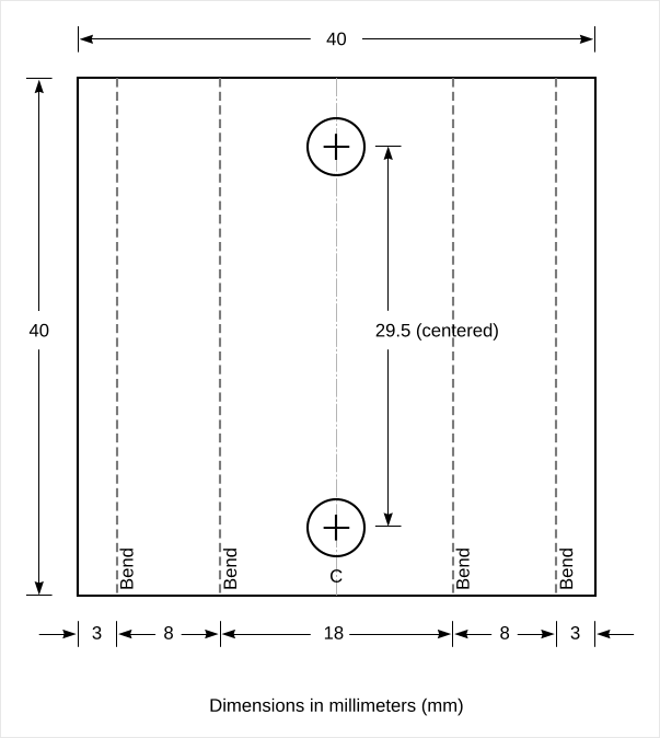
The new pressure clip was fashioned from a scrap of 20 gauge (0.81mm) aluminum sheet. See this diagram for dimensions. The aluminum is fairly easy to bend by hand when fastened in a small vise. Tapping a hammer along the crease results in a good sharp bend. The shape I decided on requires that the bends be a little more acute than 90 degrees, so a pair of pliers helped to finish the job. I used that shape to lessen the possibility that the clip might spread outwards when tightened.
[In the comments below: Harvey suggests using a half-section of plastic pipe for the clip. An excellent alternative to this metal one I fashioned.]
Small strips of self-adhesive foam cushioning material finish out the new clip.


Re-assembly begins after two holes for the screw heads are made in the rubber spacer that goes behind the LCD. To avoid breakage, I did not actually install the LCD and snap the bezel on until ready to test.
Using screws instead of the old perfectly-sized plastic posts allows the arrangement to wobble around more than before. Care has to be taken to get it positioned so that the LCD and the processor chip will be directly aligned over their respective PCB contact pads.
Eep, Opp, Ork
The first power-on test resulted in meaningless garbage on the display, but I noted that the LCD bracket had moved off-center a bit, so after loosening the nuts and straightening the bracket, the meter started to show a normal display. The nuts were then given a final tightening. Note that the metal clip and screws can provide more pressure than with the original parts, so over-tightening should be avoided.


Another old Beckman saved from the scrap heap!
Update Oct-2016 Reader Wayne C. writes in to describe an alternative procedure using the original pressure clip, which in his case was not broken:
Instead of carving out the claw-posts as you did, I left them intact and drilled through their centers with a hole big enough to pass a #2-56 screw (on the drill press this can be done quite precisely). I was able to use the original “W” shaped pressure clamp which isn’t cracked or broken. Two small washers and hex nuts holding it all together completed the repair. I didn’t have to do the machining work you did on the screws nor did I have to worry about centering them since I drilled through the centre of the existing alignment posts. Also, you can put a lot of torque on the #8-32 screws you used with catastrophic results, my #2-56 screws are a lot safer because you really can’t tighten them that much.
AL-yoo-MIN-ee-um, lol, Im sending the men in the white coats for you 🙂
Can you say solder “Sold-errrrrr”without it sounding like “Sod her” lol, to sod someone is to put something where it should no be, if you get my drift lol 🙂
Love the replacement clamp, heavy duty or what 🙂
I had similar thoughts, i would worry about the metal capacitively coupling display data to the inputs, i would have cut a small grey plastic water pipe down the center to produce a half round bridge section, sand paper on a block of wood would have made the bridge sit flat, the screws would be the same as yours but a couple of springs on the thread ends then the nuts on top.
Ive done the spring idea in the past to keep pressure applied without excess.
Smashing writeup, Dam good meter, into the wheelbarrow of excellence it goes lol 🙂
Yes, I’m a soddering fool. Lead is an essential nutrient, right?
I really like your half-pipe idea, wish I’d thought of it. Of course not being a plumber, I have no pipe scraps around here.
It did occur to me about the capacitive effects of the metal, but I was already committed (no jokes please) at that point, so I went ahead with it. In the end, it seems to have no effect on the operation. Probably less capacitance than a parallel PCB track anyway.
lol, Oh yes the lead content keeps you dafter than a politition 🙂
Its a very unusual way to hold a blobchip down, but its lasted a long time before cracking up, so i cant moan about the design, well i can as im from the uk but…. lol.
Some of the capacitors around that adc look suspiciously similar values to the ones used in the icl7106 types, i do like the old tech as its easyer to understand and repair.
Like my old fluke 8050a, ive boiled down the schematic to only the resistance side, makes it easyer for dumb plonkers like me to absorb 🙂
I can see your love for older meters, keep up the good work mate 🙂
This is a brilliant article it is so nice to be able to repair items in this throw away world and with your advice and articles it is invalueable.please keep up the good work.Best Regards N Clark.BRISTOL
Thanks for your kind remarks. As long as there is glue and solder, some of us will keep fixing things!
My beckman 110 read 1888 in broken numbers on all scales (after I droped it )
found plastic holddown clamp broken, repaired same using plastic pipe.
numbers are solid and unbroken, but still reads 1888 all scales.
I can not find my book
please comment
Check the obvious things first, like the alignment of the processor chip with the board, and look for anything else that could have been damaged by inertia in the drop, like the delicate rotary switch leafs.
I would also check for a running clock. Many DMMs use crystals which are susceptible to shock damage, but I don’t see one in this unit, so it must be an R/C generated clock. There is a 14-pin DIP CD4070 near the LCD/processor stack. (This may be missing on some models, but there is an empty footprint there.) On Pin 8 of that chip (or footprint) there should be a nice square wave of about 3Vrms 200Hz, with respect to the COM jack. If that isn’t running, then nothing is going to work.
Hi Mr modemhead.I have a Beckman HD110 which has a fault it takes a long time to zero on the diode range and the 2volt dc range. Does the one electrolytic capacitor I can see have any bearing on this and do they fail .the meter has not been used for a long while. It has no visual damage that I can see. Thanks for your advice in the past.regards N Clark.Bristol
All older electrolytics are subject to leakage and failure of course. But in my limited experience with old Beckmans, I haven’t found one that actually failed. Also I think that cap is used to filter the output of the AC converter, and shouldn’t have an effect on your problem. Caps are cheap, so if there’s ever any doubt, just replace it anyway.
If you’ve poked around this website much, you will know that cleaning everything with isopropyl alcohol is the first order of business,especially when the readings are unsteady. Current leakage in the high-impedance sections of the circuit board can cause all manner of problems. I’ve also found that the rotary switch design on these Beckmans are quite sensitive to shock and any sort of contamination on the contacts. They’re hard to clean without lots of work, but sometimes cranking the switch all the way around a few times like you’re winding a clock will clear up “funnies”. This is why I prefer old Flukes to old Beckmans. 🙂
Hi thanks for your reply as always very helpful. Keep up the good work. Best regards N Clark. Bristol
I have beckman hd 100,Its LCD display screen turn black at its centre , I want another one http://www.richardsradios.co.uk/Images/beckman%20hd1001.jpg,this is the picture of it, so thanks
http://www.richardsradios.co.uk/beckmanhd100.html ,This is the picture of the LCD displayscreen
Hello Mr. Mohamed Kamal!
Did you found LCD displayscreen for your multimeter>
I have the same problem with mine and I can’t find display.
Thank you!
Try eBay, there are people with Beckman meters including the HD100 that want to sell their meters. If you are patient some go for several dollars for parts. But I highly recommend you stick with the Beckman HD100 replacement so you don’t run into trouble, since the heavy duty meters are different than the regular industrial ones.
I’m a great fan of these Beckman Tech range of meters. Much better than the usual mega-bux autoranging stuff around now.
I have four of them, my original I bought 30+ years ago is still in daily service and wouldn’t be without it! Ive a near unused one that I keep in its original box for emergencies!
I have two with cracked LCD displays which still work but there’s a black halo slowly creeping across the display, but have maybe found a source of them. Ive ordered a couple to see if they are the same…
I have to say it would be remarkable if you have found a source of replacement LCDs for these old Beckman instruments. But it would definitely make many people very happy if you are successful. Thanks for this report and also thanks in advance for sharing your results!
Here’s the link to the ebay part, the seller reckons they came from a Beckman service place–so I live in hope–
http://www.ebay.co.uk/itm/251662269419?_trksid=p2060353.m2749.l2649&ssPageName=STRK%3AMEBIDX%3AIT
Well–Those LCD arrived–but are completely unsuitable, way too small….Shame.
Ive had success fitting a cheapo LCD from ebay, –just to prove concept. It however, doesn’t have an ‘ohms’ symbol, so on this experiment I used ‘lo-bat’ in place of that. Display works faultlessly otherwise.
The Beckman display is 50 x 30 mm and is 3 and 1/2 digit. This is easy to find, some with lo-bat some without, some with word ‘over’ and lo-batt, but Ive not had any luck finding a display with an ‘ohms’ symbol or word similar to the Beckman in this simple format and size display. The least objectionable non-original display appears to be one that has an Arrow symbol, where the ohms symbol would be on Beckman, and all other parts similar…
Hard-wiring the cheapo-ebay display was easy enough, soldering directly to display pins as they are DIL pinned and doing away with the elastomeric conductor, and at least the meter is now fully functional and readable.
I’ll get a couple of the type with an arrow symbol, RS Stock-Number, 184-7709, and do the other meter with it….
That’s too bad, it would have been great if that was the right one. It could still happen I suppose. A couple years or so ago, someone uncovered a large stash of direct replacement LCDs for some of the older Fluke models (29-II, 79-II, 76) and sold them in lots on eBay. They’re still available in singles now.
At least you got your Beckman going again with the generic LCD, which is the next best thing.
Been thinking about this problem and trying to come up with something a bit better than using an arrow symbol or ‘lo-bat’ to indicate ohms which is my only other option.
(I find the ohms symbol most useful, for some jobs, cant be without it!)
–There’s a 5 digit display by Lumix thats physically similar size to Beckman. +_ 0.5mm, its part-number, LCD-S501C39TR. Cheap common display from Mouser and others etc, with no other symbols, Just five digits of seven segment.
–Here’s a mad idea– The first digit on the left, if I was to use the top and two sides of the seven segment, we have an n–Could be sorta like an Ohms symbol–If you dont look too close, prob. better than a non sensical arrow…
Easy to wire up, and digits are only 2mm smaller height wise to original Beckman from what I can find, Maybe it’ll look a bit odd have to see….
Its just a mad idea. Ill give it a try, Ive got another dodgy looking Beckman coming I won cheap off ebay with disply-rot, bought for its chip mainly (270-100) as Ive one in whats basically a spares-dog as its so poor condition, with non functional AC ranges…
Ive taken the cheapo-ebay display meter, 3020 into work, its serving well so far, giving my original trusty 30 year service Beckman Tech 310 a well deserved rest!
I like it! What about a “c” for continuity?
‘C’ is even better!
One thing I did think of was the loss of the plus/minus symbol in that display, I could have a Minus, but it would be present all the time on DC ranges….
–Plus part in Beckman relies on a colon above/below the minus…
The trick is to allow the minus sign to be ON only if the plus/colon is OFF. I tried to scratch out something to do that, and it takes way too many gates to be a simple hack. Have to think about it some more…
Ok, I think this will work. It would require hacking in one quad XOR gate CMOS package (4070, etc.) When the PLUS (colon) is ON, it will be out of phase with the backplane (BP) signal, and will produce a logic high out of the first XOR gate. That will cause the second XOR gate to invert the MINUS signal, thus turning it OFF. If the PLUS is OFF, the MINUS signal passes through unchanged.
Beckman generic LCD hack circuit
Wow!
Thanks for the input!
I was considering a simple two-input CMOS NAND Gate, Powered by the Minus symbol data-pin (5V?) and also one input monitoring the Minus the other the colon.
Hence–If Colon is off (reading a neg voltage,), we get output to drive Minus when minus is present on meter jack.
No minus–No supply to Nand-gate, and no output.
Colon on and minus on would give normal ‘NAND gate’ action and give no output (plus)
Having Never done Any digital stuff at all–what do you reckon?
Not sure where the neg-supply for gate would come from–prolly Not BP as this would upset it. Maybe colon or DC chassis. Dunno…
All this weird switching in/out of phase stuff gets confusing…
LCDs are not driven with steady logic levels, so your method will not work. LCD segments can be damaged if you apply a steady DC voltage across them. All of the LCD drive signals are actually 200Hz square waves. The voltage probably varies with model, but in this HD110 I have handy, the square wave goes from 0V to 6.4V according to my scope. Do you have a oscilloscope? It would be handy.
The LCD has an input for each segment, plus a “common” line called the backplane (BP), which is also driven with a 200Hz square wave. A segment to be turned ON should have its square wave inverted (180 out of phase) with respect to BP. A segment to be turned OFF should have it’s square wave exactly in phase with BP. This drive method insures that each segment sees an average voltage of zero, whether it’s ON or OFF.
Any CMOS logic added to drive the LCD should be powered between ground (Vss) and the meter’s positive rail (Vdd), which I presume is about 6.4V. Ground tracks are available all over the board. The COM jack is tied to ground. A suitable pick-up point for Vdd would have to be identified.
I may have another alternative, Ive found a better disply….
A 4.5 digit display with colon and a minus, so no need for gates to drive the minus…
http://docs-europe.electrocomponents.com/webdocs/144d/0900766b8144dad0.pdf
Thanks for your article and pictures. I have a Tech 300 which, after many years of faithful service, stopped working while I was changing the fuse. I must have somehow broke the clips holding the stack together, although I haven’t the foggiest idea how I did or when I did. The comment about having to hold the stack together very firmly was useful.
Any words of wisdom on how to handle / maintain / … the elastomeric strips? I am worried about damaging them when I disassemble things to chop off the plastic bits and insert screws. Thanks.
Some people like to clean them with pencil erasers or microfiber towels, but I much prefer isopropyl alcohol (IPA). Then handle with tweezers to keep the skin oils off. Some models have rectangular strips, but some have round strips, which I’ve found may take some fiddling with to find a position in which they work.
Thanks for that advice, and I’m sorry I didn’t follow up before now.
Like Wayne C, my pressure clip was not broken, just the “claws” that hold it on. Also like Wayne C, I decided to use screws. In my case I drilled out the middle of the claw posts just enough to fit in a #4 screw in each, which I epoxied in place after removing the screw head. The clip fit down over this, and a washer and a nut on each side did the trick. I first tightened up the screws a bit, tried it out, and discovered I needed a tiny bit more tightening to get all the display segments displayed.
This procedure was a bit less “invasive” than yours (I wasn’t as brave as you, even with your advice!), and I figured if it didn’t work or if the posts broke, then your complete post replacement would be the next step.
In any case, I’m really happy I found your description, the meter has been happily functioning with this repair for a few years now.
i have a Beckman hd100 meter, when turned on it starts giving false readings before even being connect to anything. it goes up and down until you turn off. changing the battery does not make a difference.
All Beckman repairs should start with a thorough clean-up. Use IPA (>90% isopropyl alcohol) on the elastomeric connectors for the LCD and main chip. Use compressed air for the rather delicate range switch leafs. In my limited experience, this clears up most of the funny readings and odd behaviors on these meters. There are lots of pictures around here that may help.
Hi guys, many thanks for the hints and tips about fixing Beckman DVMs. I had a tec 310 for over 35 years but recently “lost” it! Being old school (obviously), I can never get on with the new fangled auto ranging meters so I looked on e-bay and picked up a Tec 330 as working. Well it almost worked but the display was displaying random numbers.
I took your advise, took out the display and cleaned the contacts. It took two goes to get it together but now is fine! Interesting to see the chip and elastomeric connectors are gold but the PCB looks like just tinned tracks – no gold.
One question regarding calibration. I see there is a pot for adjusting the RMS zero and gain. Is it ok to use a DC source to check the RMS ranges?
Thanks again
Graham
Good job getting the 330 going again. AC voltage ranges (RMS or not) are usually AC-coupled with a series capacitor, so DC won’t work. A computer sound card playing a sine wave tone is a decent stable source for low-voltage AC.
I was looking for repair parts for my Beckman HD110 when I came across your site. I had exactly the same problem with my meter, and have tried different ideas over the past few years to repair it. Back up on the shelf it would go, till I’d have another idea to fix it. My story; I was a radio repairer (old 31E, or 31 Everything) in the Army and my first assignment was to the 2nd Infantry Division in Korea. The unit I was in maintained sites on the DMZ and radio communications was very important. I fixed a lot of radios and equipment that year in our camp, in the field and up on the DMZ. When I was home on mid tour leave, I went to an electronics store in Harrisburg Pennsylvania and bought this HD110, used it the rest of my time in the Army including a second tour in the 2ID in Korea. Getting rid of it was not an option as this has a lot of value (sentimental and otherwise) to me and getting it work again is great. The only repair that I had done prior was to replace the case, and honestly I wish I would have kept the old one as the case around the thread inserts cracked and had to be epoxied in place. To repair the display bracket I followed your instructions but happened to have some 3/4 pvc pipe, and to avoid shorting I used nylon screws and nuts. I cannot thank you enough for coming up with such a great fix.
I have a Beckman 310 but the screen is almost unreadable because the background has become dark. The digits read fine but cant see them well. Any replacement glass screens or a way to replace the back ground? TKU David
THANK YOU for posting this. I was about to throw out a HD100 I had bought at auction ($20) which has the rotten plastic problem. I’m glad I didn’t.
I’m going to try the plastic pipe clamp, and I’ll be using nylon hardware instead of steel, both for insulation and for better elasticity.
Friends, I have a Tech 360 multimeter, but the display is totally dark. Please, does anyone know the display part number? Thanks in advance.
Hello, love seeing others who love their old Beckmans! I had a couple and eventually got to the point where cleaning the contacts and the elastomeric strips (zebra strips) are just worn out. After years of searching, I found a stash of them. The older meters will have a very skinny pair for the cpu and newer ones, or factory repaired ones may have a much wider pair. I’ve found that for the skinny set up these work great, and for the wide ones I put 3 of these standing next to each other and put them in place just like they are 1 wide one. So far so good. If my prototypes keep working well (I have 6 working), then I can start selling the strips. They really make a difference in how much clamping force is needed. Mine are all working with the original ZZ type holder, and 1 or 2 have a newer type I haven’t seen before, it looks like what someone else did with half a pvc pipe, but this is from the factory. I can send a pic if you would like.
I’m working on a Beckman 360 meter. The display works great, the problem is AC voltage and current–no go. Displays 0.00 with a blinking decimal. I have found that the -5 V supply reads -1.40 V. Tried clamping the voltage to -5V to no avail. Tantalum caps and electrolytic cap are fine. Can someone enlighten me as to where the -5 V supply comes from? Most of the supply voltages are +6.5 V. The circuit seems close to the Beckman 330. I have injected AC into the meter and traced it to the input of the AC converter chip. But without -5 V supply I am dead in the water! Appreciate anyone’s thoughts. I have another 360 on the way, so hoping for better results. I bought my Beckman 310 new in 1979 and it still works like a champ. Such a pleasure to use. Thanks to all, William
Double check that the 3 5-piece ribbon cables are good in continuity, especially the one close to the battery.
Hi,
Many years ago i bought a Beckman 3020. Had a display contact problem (after a few yaers) and solved it the way as decribed in some previous posts, using a thin u-shaped aluminium curtain rail.
I am looking for new matching test leads, hard to find in Europe.
Can you recommend any?
regs
Eddy
Eddy (or anyone else still listening), did you ever find any test leads compatible with your Beckman? Mine look like they are thinking about giving up the ghost (next to the strain relief at the meter end), and it seems all the “fits every meter” leads I can find have much smaller shrouds around the banana plug.
Hi, i have a td850 meter and the screen is starting to bleed, can you advise i can get a replacement for it.
The seller failed to say that the display had a problem, not some honest people out there huh..
hi i like beckman hd153 meters i had one for years still works i would like to buy another but hard to come buy
Good day, thanks to this page I was able to repair a Beckman 360 table top multimeter. It finally had 3 problems: the display, damaged threads, cracked contact.
The display was repaired by drilling a 2mm hole through the 2 posts and securing the parts with 2mm bolts as suggested.
The damaged threads on both sides of the “wiper” assembly of the rotary knob was fixed by pushing a thin rubber tube (taken from an electrical wire). In that way, the screws were able to get a hold and squeeze the 2 halves together. I also cleaned the wipers with contact spray (as I did not wanted to take the risk of taking that apart).
The cracked contact was on 1 of the 3 5-piece ribbon cables connecting both halves. A bit of solder fixed that.
Prior to the fixes, I had troubles with the display, but also a non steady reading of high value risistances. I suspect that this was caused by poor contact of the wipers, but I have no proof (having fixed at the same time the cracked ribbon cable).
Now it is working like a charm and it seems still spot on in accuracy after all these years.
Keep up the good reporting!