
 There seems to be a trend in Fluke repairs here lately. Other than your occasional fusible resistor, the problems seem to be related to materials instead of electronic bits. Cracked and broken plastic, and metal fatigue. Are these design problems, or is it that people use these devices so heavily for so long, that the finite lifetime of these metal and plastic parts is exceeded? Well you be the judge of that, I’ll just look for a way to make repairs.
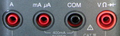
Today’s issue concerns the jack assembly for the Fluke 80-series of DMMS including the 83, 85, 87, and 88 models. Instead of individual 4mm banana jacks, there is a single molded assembly containing all four jack ports. Each jack consists of two half-round contacts inside a red or black colored shroud. The two separate contacts are used to detect when a plug is inserted in the A or mA jacks on the left side. Inserting a plug shorts the two halves, which is detected by the meter and results in a chirping sound when the rotary switch is set for anything other than current measurement.

This problem seems to affect the COM and V+ jacks the most, because they are used the most. Fortunately those two jacks do not actually need to have the two separate halves and indeed the pairs are soldered to the same point on the circuit board. So that allows for the repair described here, where a single piece of brass tubing will be substituted for the original contacts. Brass tubing is readily available, and solders well. And aside from a little tedious grinding, it makes for a reasonably quick repair without having to spend $$$ for a new jack assembly.
Tools required for the procedure include a 5/32″ (4mm) drill bit, a 3/16″ (4.8mm) drill bit, and a pin vise. I like to use a pin vise instead of a powered drill because it reduces the chances of an “oops” moment where the bit snags and you end up breaking the piece you’re working on. A rotary tool such as a Dremel or Proxxon is essential for cutting and shaping the brass tubing.


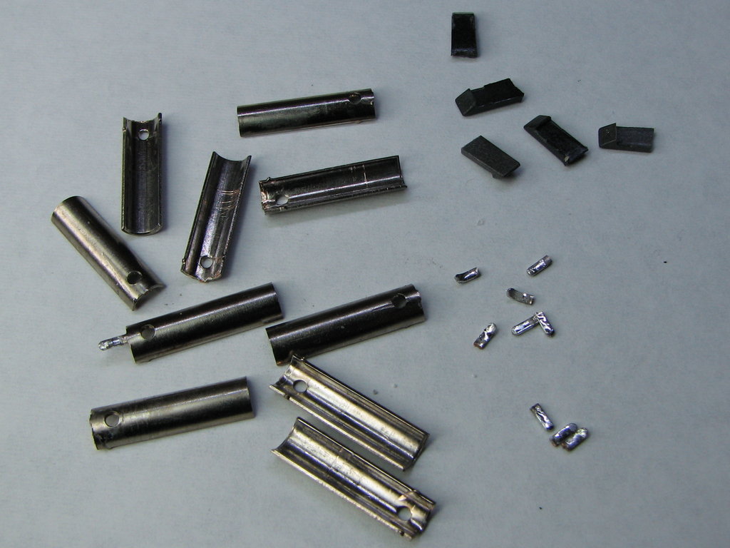
First, the old contacts have to be removed. This is done by drilling out the plastic at the back of the port with the 5/32″ drill bit. Each contact is then dislodged by tapping with a hammer and screwdriver and pushed out of the back side. Do not attempt to remove them from the front because the plastic shroud’s inside diameter is narrower there.
This will leave two ridges, and two little bumps of plastic where there were holes in the contacts. This material can be reamed out with the 3/16″ drill bit. A twist drill makes a lousy reamer for this tough plastic, so the interior will be rough, but that will not be a problem. The original contacts are 17mm long, so the drill bit should not be allowed to go deeper than that, or the plastic inner shroud will be damaged.


Next, the replacement jack tubes are fabricated from brass tubing stock. A piece of tubing cut 21mm long, with 4mm lugs ground on one end, will leave 17mm to insert in place of the old contacts. For my initial effort pictured here, I used 20mm with 3mm lugs, but that was cutting it a bit close, so I suggest an extra 1mm to be sure.


The completed jack tubes are secured inside the jack assembly by smearing with cyanoacrylate gel (thick superglue) and pushing into place. The jack tube will be securely held in place by soldering to the circuit board later, so this glue is basically for filling the gaps and holding the tubes in place for the rest of the repair process.
Now the back ends of the jack tubes are re-sealed using some quick-set epoxy (JB-Weld Kwik, in this case.) To keep the epoxy from oozing down into the jack tubes and causing an obstruction, plugs are made from cotton buds coated with petroleum jelly. The stick makes a convenient handle to remove the plugs later. After the epoxy starts to set, the excess is trimmed so that the jack assembly will still set flush on the circuit board.

")


This repair should be practically undetectable from the front, aside from the full-cylinder brass tube instead of the original split plated contacts. Before soldering the rebuilt assembly back on the circuit board, the new lugs are scraped to insure no epoxy material is stuck there, which would make soldering difficult. I used a liberal coat of flux and a 350ºC iron with a 1.6mm chisel tip to securely solder the assembly back on the circuit board.
Testing with a shorting bar shows that the resistance is the same as it is for a normal unit (0.0 to 0.2 ohms).


The longevity of this repair is unknown and up for debate, obviously. I would not expect the brass tube to be quite as sturdy the original contacts which appear to be beryllium-copper (a guess.) But by exercising caution when inserting and removing plugs I expect it could last a good long time. Repair or no repair, it’s always a good idea to avoid sideways stresses by not tugging on the leads too much.
Smashing repair and by the looks of it very strong.
The cement you used to fix the replacement tube in looks solid and water tight, so i cant see it causing any problems really.
I also dont think it will make any difference to the insulation propertys of the socket, your skill in removing just the core of the socket without removing the plastic wont change the design one bit.
And the method of pcb mounting hasnt changed, stronger than the original.
Thou shalt not incur the wrath of the Internet Safety Police, as my grandpappy Charlie Yankee Alpha used to say.
Well you know what the internet police can do with there opinions lol 🙂
Nuff said 🙂
I agree with Harvey. Very nice, high quality presentation! I would have no trouble following it.
I wonder, though, if you have any ideas for my situation. I bought an 87V on ebay that seemed to work fine until I needed to take a current reading. I couldn’t get one, so I checked the DMM-44/100 fuse, which was open. Ordered another fuse, and when I put it in, the beeping reported here and elsewhere began, regardless of whether there was a lead inserted in the jack or not, even with a lead in the common and either current jack when set on either current setting. It is now clear why they put a bad fuse in the meter. There is no beeping when the bad fuse is in place, and all other meter functions work besides the current ones.
I pulled the jack per your instructions, but all the leads were solid and with good continuity. Soldered it back onto the board–no change to the incessant beeping.
Any ideas? Any other resources you know of that might be helpful?
Thank you Modemhead …..My 189 had been recovered from a Skip……….When I opened it the batteries were a mess, and they had corroded the Phosphor Bronze contacts , I
made a new set from shim brass , and the meter was basically working BUT with theLeads error ………I resoldered the current terminals and all is well . regards from Bernie Vk2abn
Very skillful repair.
I’m having the same issue on a 87 IV I found in the dumpster and I’m halfly considering turning it around so to disable the Amper (we have cool clamps for that now-a-days). But then again your solution is elegant so I will try both turning them around AND replacing the broken ones.
This way my repair will last longer inshallah 🙂
One question though. What is the diameter of the stock brass you used? Here in europe I can only find 4mm and 6 (outer diam) with 0,5material thickness. Our banana jacks are 4mm inner diameter, so Im a bit stuck 🙂
cheers and thanks again
PS paying the 40euros for the new part is out of question 🙂
My tubing is 3/16 inch OD. It works out as 4.76mm OD, and 3.95mm ID, which is nearly perfect for standard 4mm banana plugs. I hope you can find some in this size.
Please note: doing this repair AND turning the jack assembly around will not work, because the repaired jacks will not be split in half like the originals. This will cause the meter to think that probes are plugged into the A and mA jacks, and it will signal the LEAD alarm.
Thank you very much, you are damn lucky with your imperial units 😉
We only have 4-6mm (OD) here, so I will try my luck by getting the 4 and then cutting in half to emulate the two halfs and create some flexibility because originally my tube will be 3mm (ID) AND turn it around 🙂
I hope my 3d printer will help me stabilize everything and I will post my progress with pictures in this thread here for people who find it interesting
https://www.eevblog.com/forum/repair/fluke-87-iv-repaircleaning-questions/
What I am NOT going to do is pay 40euros for this piece of plastic, so worst case scenario, I will have a fluke without mA A abilities which I rarely use these days of the clamp meter convenience.
Thanks again your site is a paradise for hackers who are not afraid to commit profanities to holy flukes 🙂
I have seen the broken jack issue at work, too.
The colleagues use standard straight lab cables for measuring a lot, I try to avoid this and use the right angled cables as far as possible.
The straight plugs put a lot of stress on the jack assembly.
Looking for display unit of my fluke 87, can you send me the price quotaion.
Thanks for the clear handout.
What I did was after I drilled the 4mm thru the powerbus, I inspected the inside and noted that the remaining 2 halves where kept in place by 2 notches.
So I drilled these notches away with a 2mm drill, and out came the 2 halves.
I ordered on Amazon a brass pipe with OD 5mm and ID 4mm.
For the rest I followed the handout and all worked perfect.
A big thanks from The Netherlands.